

LED lighting system with bypass circuit for failed LED
a technology of bypass circuit and led lighting, which is applied in the field of led lighting, can solve the problems of failure of leds in series, failure of others in series with leds, etc., and achieve the effect of relatively low cost of solution
Active Publication Date: 2013-04-02
RINGDALE INC
View PDF11 Cites 15 Cited by
- Summary
- Abstract
- Description
- Claims
- Application Information
AI Technical Summary
Benefits of technology
The patent describes a solution that is cost-effective and can be used for groups of LEDs or individual LEDs.
Problems solved by technology
Although LEDs, in general, are reliable for extended periods of time, failures are known to happen.
If one LED fails and becomes an open circuit, then the others in series with that LED will also fail because no current can flow.
Method used
View moreImage
Smart ImageViewing Examples

Examples
example 1
Circuitry Provided With Each LED
[0031]In this example, the bypass circuit may be provided with each LED as a single unit.
example 2
Circuitry Provided as Integrated Circuit
[0032]In this example, the bypass circuit may be provided as an integrated circuit that is subsequently wired in parallel to each LED.
example 3
Discrete Components
[0033]In this example, the bypass circuit may be provided as discrete components, such as on a circuit board, that are subsequently wired in parallel to each LED.
Login to View More PUM
 Abstract
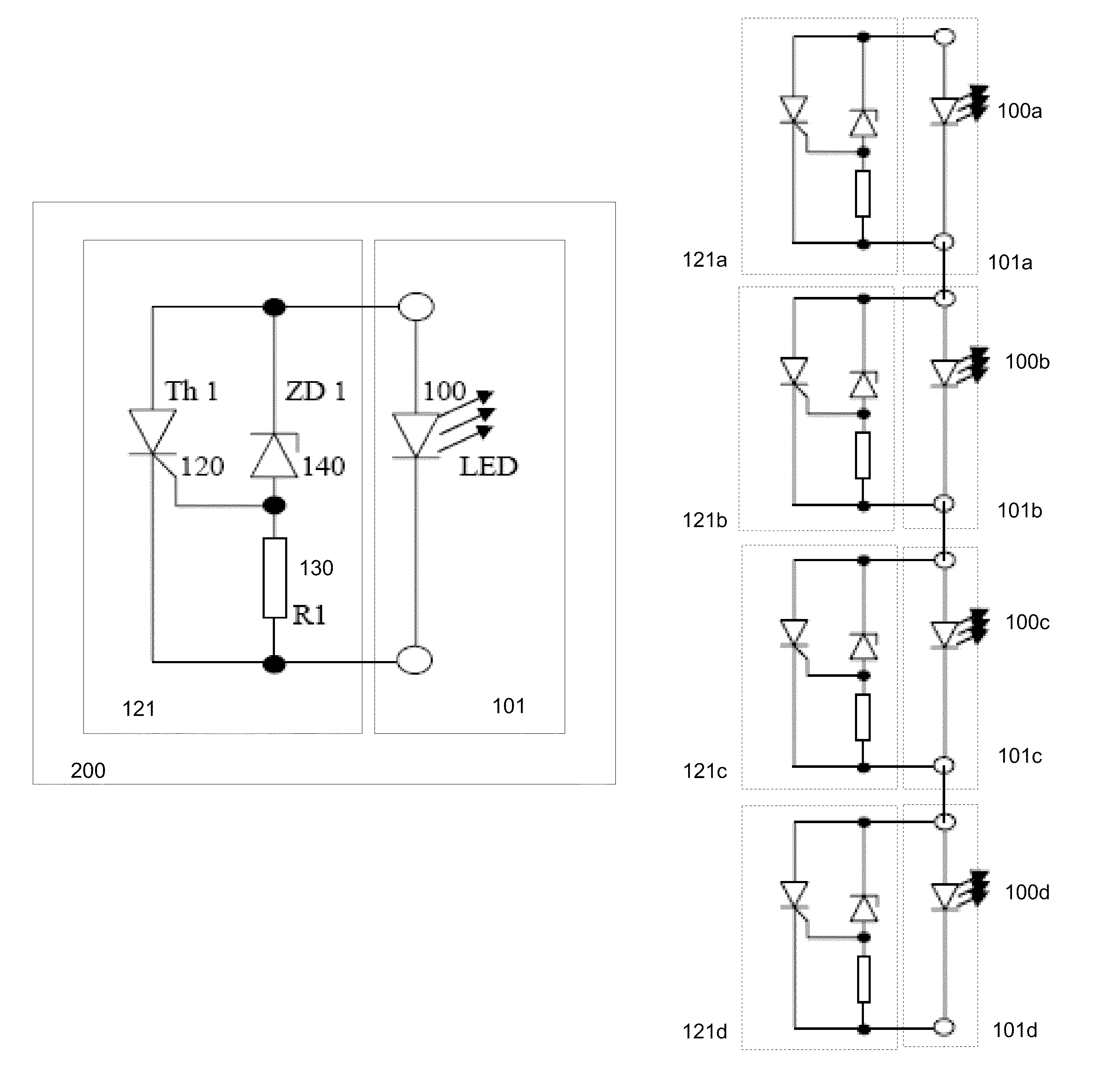
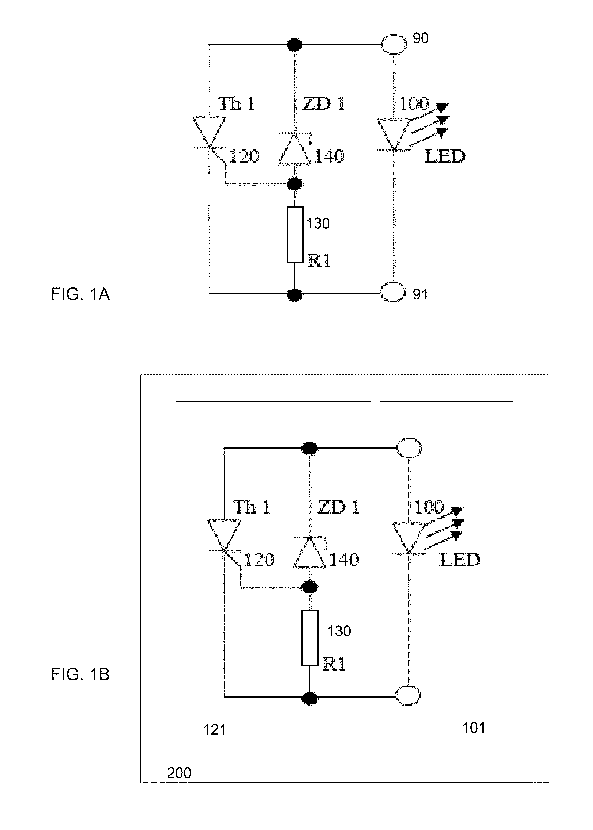
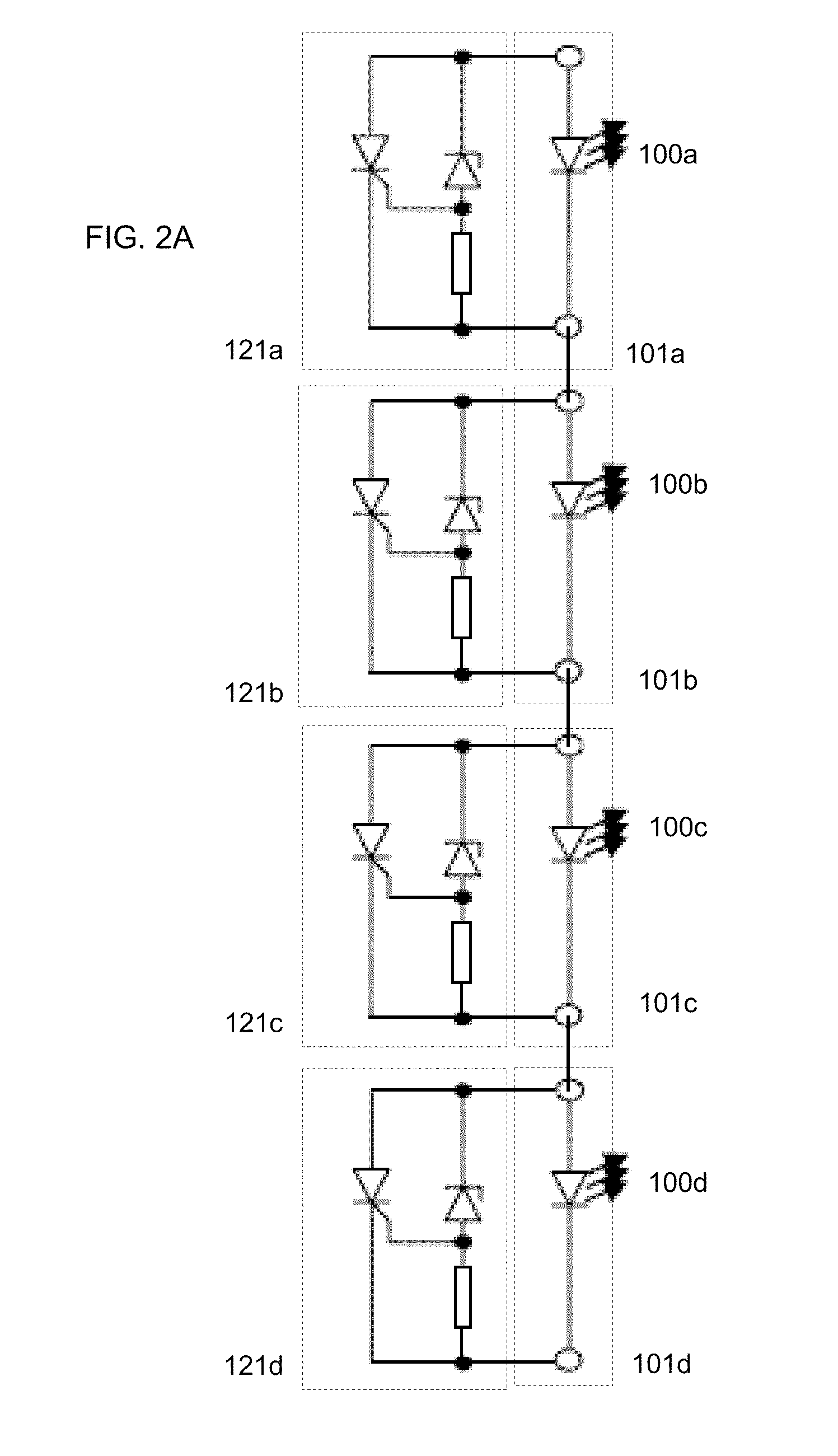
A bypass circuit is provided for each LED in a series to permit continued operation with reduced lighting in the event of an LED failure. The bypass circuit is provided in parallel to the LED and comprises a Zener Diode provided in parallel to a thyristor. Upon LED failure, the voltage across the Zener Diode is increased thereby triggering the thyristor which is maintained in a triggered mode as long as current flows through the series circuit.
Description
[0001]This application is related to U.S. Provisional Patent Application No. 61 / 115,775 filed Nov. 18, 2008, and claims the priority date of that provisional patent application;; and is related to U.S. Provisional Patent Application No. 61 / 149,076 filed Dec. 14, 2008.BACKGROUND[0002]1. Field of Invention[0003]This application is related to LED lighting, and more specifically to a system and method for providing continued operation in the event that an LED in series with other LEDs fails.[0004]2. Prior Art[0005]Most LED lighting arrangements have a number of LEDs in series. Although LEDs, in general, are reliable for extended periods of time, failures are known to happen. If one LED fails and becomes an open circuit, then the others in series with that LED will also fail because no current can flow.SUMMARY OF INVENTION[0006]The essence of the invention is to detect the failure of an LED and to shunt the open circuit LED so that the other LEDs can still function and produce the maximu...
Claims
Login to View More Application Information
Patent Timeline
 Patent Type & AuthorityPatents(United States)
IPC IPC(8): H05B37/00
CPCH05B33/0824H05B33/089H05B45/44H05B45/54
InventorBOLLMANN, KLAUSPENICK, TOM C.
OwnerRINGDALE INC