
Overload relay switch without springs

a relay switch and relay technology, applied in the direction of circuit-breaking switches, contact mechanisms, protective switch details, etc., can solve the problems of disadvantage, improvement, use of solenoid, etc., and achieve the effect of reducing complexity, less complex, and less expensiv

Active Publication Date: 2013-04-02
EATON INTELLIGENT POWER LTD
View PDF11 Cites 0 Cited by
  • Summary
  • Abstract
  • Description
  • Claims
  • Application Information

AI Technical Summary

Benefits of technology

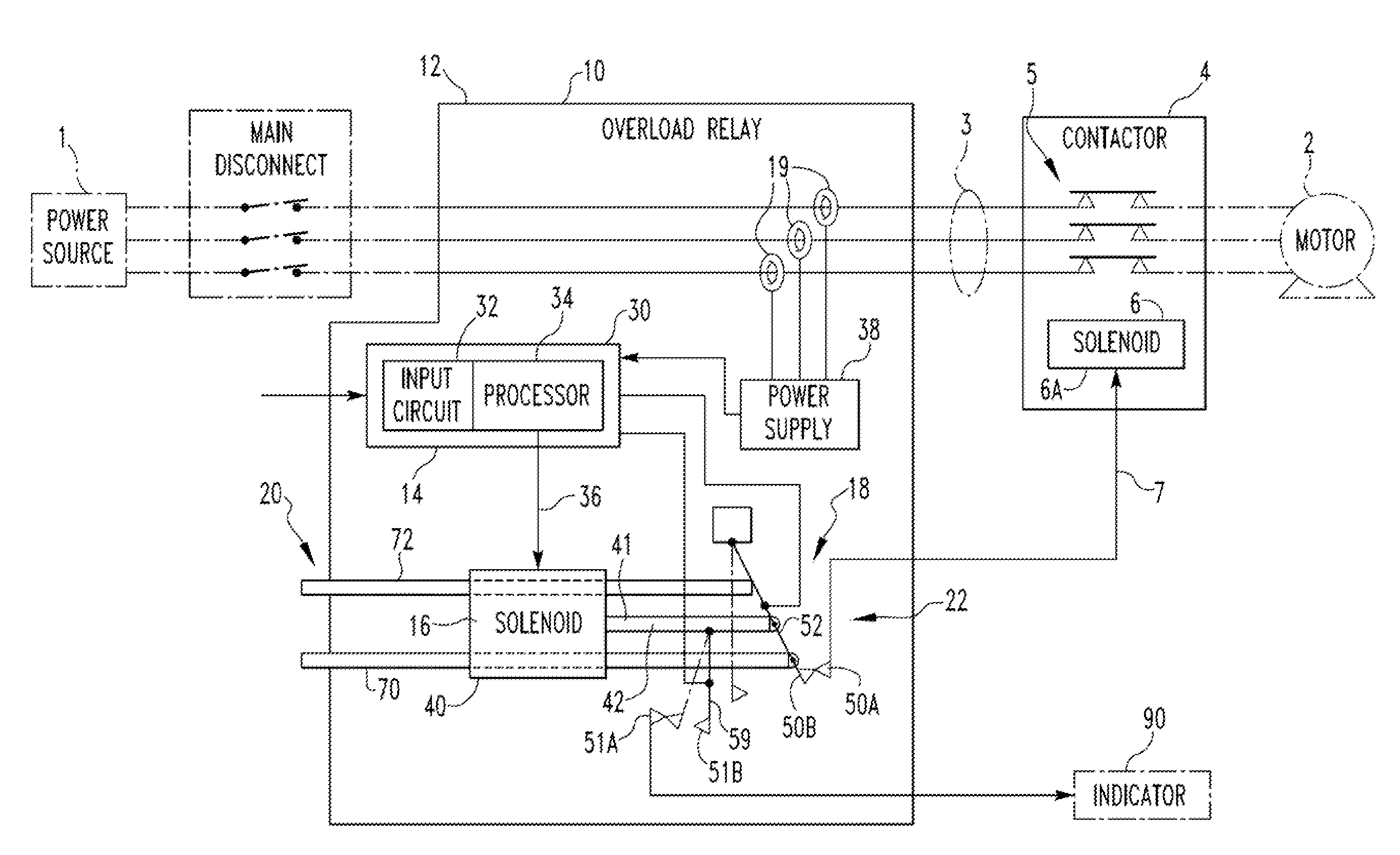
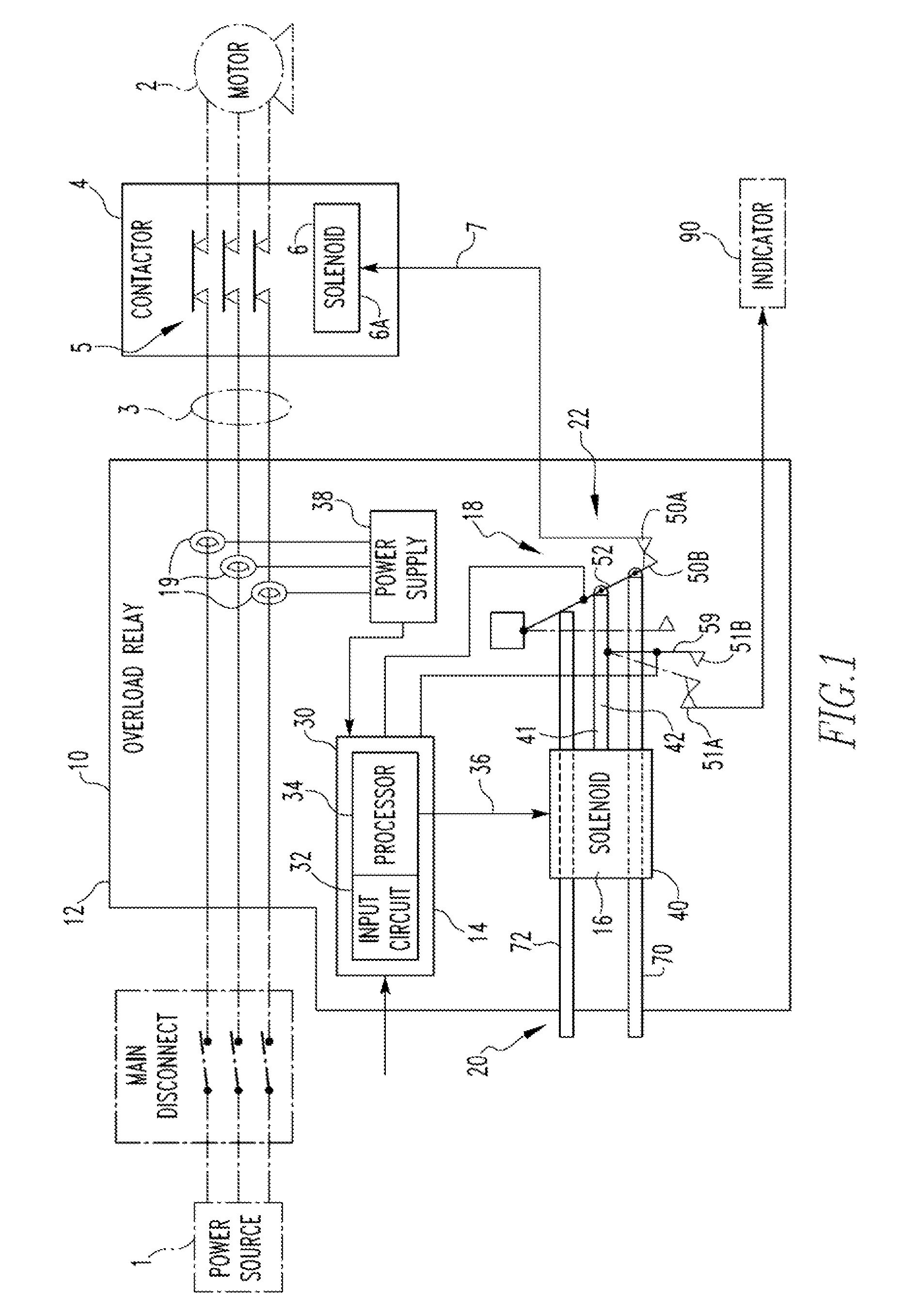
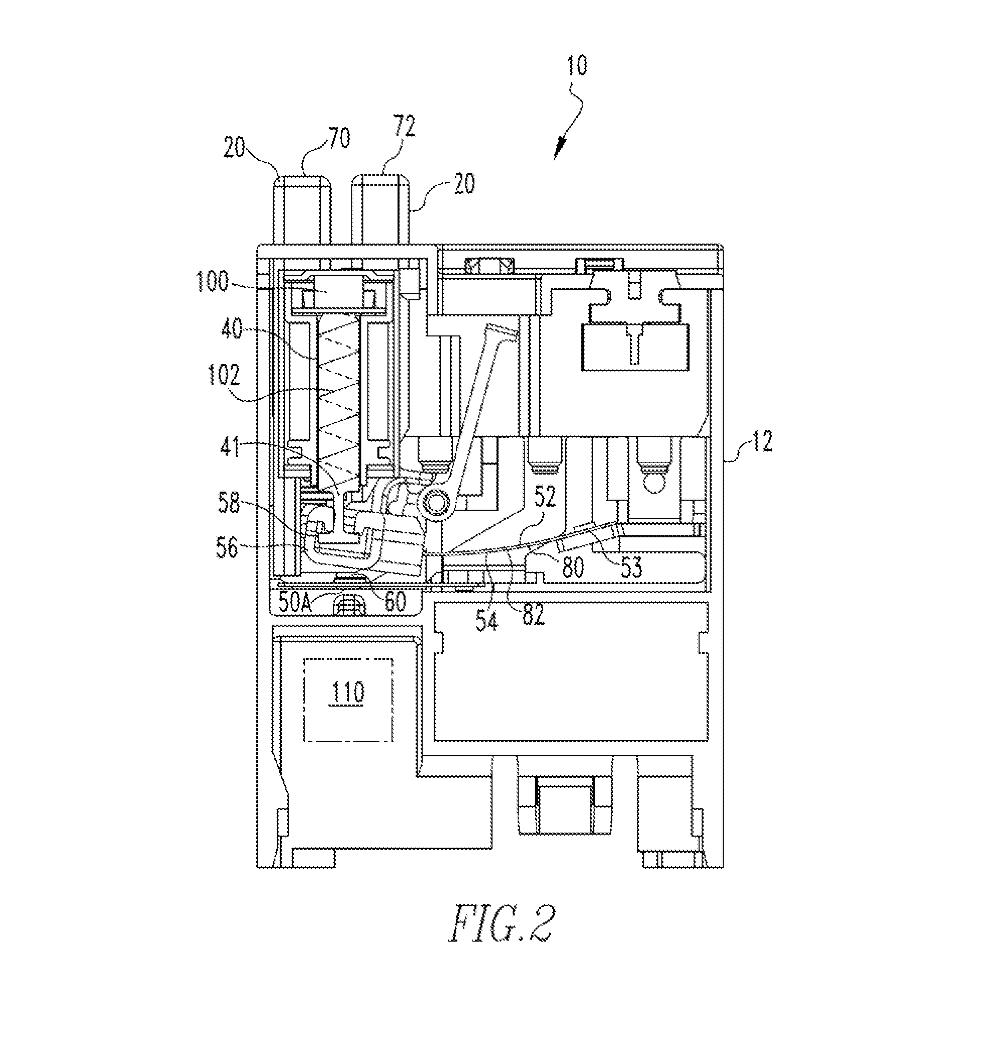
[0012]Moreover, the test and reset actuators have a reduced complexity. That is, the test and reset actuators are generally straight bodies that are slidably disposed in the relay housing. The test and reset actuators extend partially out of the housing so as to be accessible to a user. More specifically, the test and reset actuators extend partially out of the housing when needed; for the test actuator, this is when the switch assembly is in the second, close position, for the reset actuator, this is after the relay switch has been moved to the first position and needs to be reset. The test and reset actuators are, essentially, elongated members structured to be selectively coupled to one or both of the first and second switch members. For example, a test actuator is selectively coupled to the switch member by an extension that is disposed under the switch member, so that actuating the test actuator lifts the switch member and moves the switch assembly to the open configuration. If the test actuator is pushed, the extension moves away from the switch member and the switch assembly stays if the open, first position. Alternately, the reset actuator selectively engages the switch member, or a component coupled to the switch member, when the switch member is in the open, first position, and moves the switch assembly to the closed, second position. The reset actuator may be disposed substantially within the housing. If so, when the switch member moves following an over current condition, the switch member also moves the reset actuator partially out of the housing where it may be accessed by a user. After the over current condition has been eliminated, the reset actuator is moved into temporary engagement with the switch member, if not already in contact therewith. Further movement of the reset actuator moves the switch member into another position, i.e. the switch member is moved back into the operating position. At this point, the reset actuator may be maintained substantially within the housing as before. When another over-current condition occurs, the movement of the switch member to the first position will move the reset actuator out of the housing so as to be actuated again. Further, movement of the switch assembly to the second position causes the test actuator to move as well. Because these actuators are moved by the movement of the switch members, no spring or other return device is required to reposition the actuators.
[0013]Further, the complex snap switch conductive member has been replaced with a simple blade. The blade is an elongated, substantially flat member having a terminal pad adjacent one end. Because the blade does not have the “snap” feature, the blade is much less complex, and less expensive, than the known snap switch conductive member. Further, the blade is simple and inexpensive to install.

Problems solved by technology

It is noted that the use of a solenoid, while being an improvement, creates a disadvantage as well.

Method used


Image

  • Overload relay switch without springs
  • Overload relay switch without springs
  • Overload relay switch without springs

Examples


Embodiment Construction

[0022]As used herein, a “generally straight” body means an element wherein the body has a substantially constant cross-sectional shape and area extending over substantially all of the longitudinal axis of the body. That is, the body does not have a plurality of lateral extensions or cut-outs forming multiple ledges. A “generally straight” body may have a single lateral extension, offset, or flange, but not more than one.

[0023]As used herein, “coupled” means a link between two or more elements, whether direct or indirect, so long as a link occurs.

[0024]As used herein, “directly coupled” means that two elements are directly in contact with each other.

[0025]As used herein, “fixedly coupled” or “fixed” means that two components are coupled so as to move as one while maintaining a constant orientation relative to each other. The fixed components may, or may not, be directly coupled.

[0026]As used herein, “selectively coupled” means components are temporarily coupled following a selected a...


PUM


Abstract

The disclosed concept relates to an overload relay and, more specifically, to an overload relay switch having a reduced number of components and less complex components. The reduced number of components includes the lack of a return spring on the manual actuators. Further, the relay switch member, which was typically a snap switch conducting member structured to change its configuration, is a substantially flat blade. Further, a circuit is used to detect an over-current condition and a solenoid actuates the relay switch assembly, thereby eliminating the need for a mechanical over-current detection and switch actuation device.

Description

CROSS REFERENCE TO RELATED APPLICATION[0001]This application claims priority under 35 U.S.C. §119(e) to U.S. Provisional Patent Application Ser. No. 61 / 360,221, filed Jun. 30, 2010 entitled OVERLOAD RELAY SWITCH WITHOUT SPRINGS. This application is related to commonly assigned, and concurrently filed, U.S. patent application Ser. No. 13 / 165,047, filed Jun. 21, 2011, entitled “ELECTRONIC OVERLOAD RELAY SWITCH ACTUATION”.BACKGROUND OF THE INVENTION[0002]1. Field of the Invention[0003]This invention relates to an overload relay switch and, more specifically, to an overload relay switch having a reduced number of components, including not having springs, and less complex components.[0004]2. Background Information[0005]Relay switches, such as, but not limited to relay switches on motor starters, are used to interrupt power to a motor in the event of an over current condition. Typically, a power source provides electricity to the motor via a plurality of line conductors. A contactor switc...

Claims


Application Information

Patent Timeline
Patent Type & Authority Patents(United States)
IPC IPC(8): H01H73/00H01H75/00
CPCH01H71/123H01H71/125H01H71/128H01H71/58
Inventor HECKENKAMP, DANIEL PATRICK
Owner EATON INTELLIGENT POWER LTD
Learn More