Mine protection for vehicle

a vehicle and protection technology, applied in the field of vehicle protection, can solve the problems of requiring a massive support arrangement, heavy and expensive, and collapse under a mine explosion, and achieve the effects of reducing the breaking force of explosions, saving weight, and enhancing frame strength

Inactive Publication Date: 2013-04-09
KOSHELEFF PATRICK ANDREW
View PDF3 Cites 34 Cited by
  • Summary
  • Abstract
  • Description
  • Claims
  • Application Information

AI Technical Summary

Benefits of technology

[0010]These actions decrease the breaking force of the explosions and protect the driver to an extent.
[0011]The second part of the invention is to make double use of the protective structure and have it constitute the frame of the vehicle, in order to save weight. To that end, three spacers considered as longitudinal stringers are stacked vertically so that their webs add up to a deep beam of some strength. Two deep beams, spaced apart, constitute special frame means which replace a conventional frame. The wedge can be bolted to bulkheads front and rear of the driver compartment, augmenting the frame strength.
[0012]The cross section of the stack is deepest near the centerline of the vehicle, tapering off to shallower structure at its side where the stack merges with the wedge. The contour of the inside arm of the wedge is congruent to the shallow extremity of the stack. Thus, the wedge's material increases as the stack's material thins out at the edge of the stack. The wedge is configured to crush sideways under the detonation wave, absorbing more energy. Therefore, the wedge can perform an alternative protective function, which is an economy.

Problems solved by technology

His criticism is, “which require a massive support arrangement which is both heavy and expensive.” We circumvent this problem by making the spacers of the multilayer, the frame of our vehicle.
This being somewhat less than armor plate, and not reinforced, it might collapse under a mine explosion of any likely size.

Method used


Image

  • Mine protection for vehicle
  • Mine protection for vehicle
  • Mine protection for vehicle

Examples


Embodiment Construction

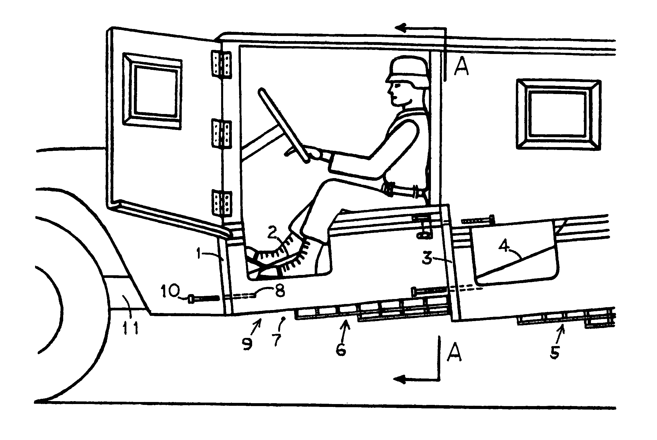
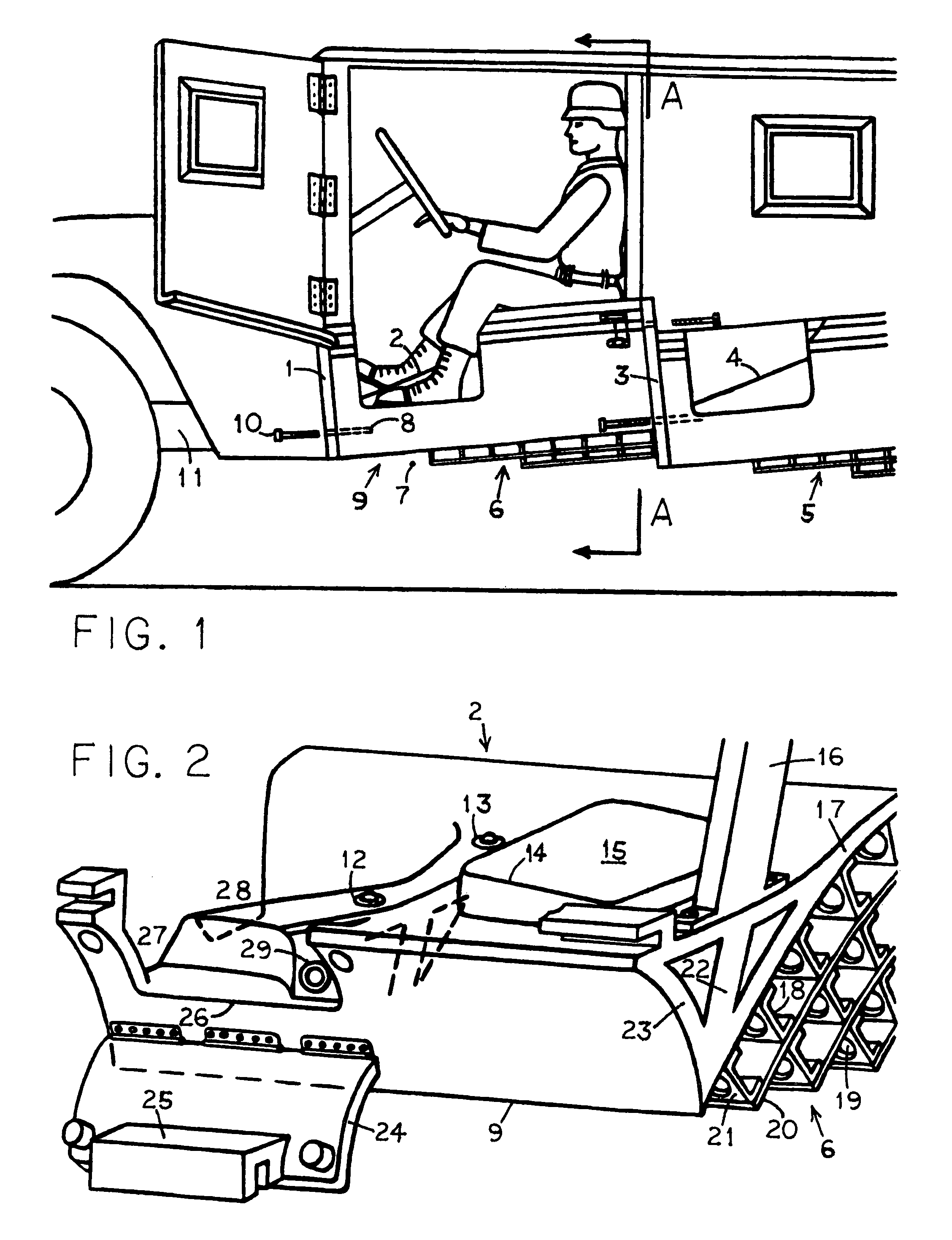
[0021]FIG. 1 is a side view of a military utility vehicle patterned after the U.S. Army's “Humvee”. Modifications are made below the passengers to protect them from mine explosions. This document will only look at driver protection. The mines are buried below or beside the vehicle, and sample explosion and damage scenarios will be shown in later figures. For now, the new equipment is designated as a stack 6 and a wedge 9. The driver sits in sculpted platform 2 which is somewhat like a bathtub, in that it encloses the driver from below. Wedge 9 is mainly intended to protect the driver from a mine explosion at the edge of the vehicle. Stack 6 will protect from a mine explosion under the vehicle. Platform 2 construction is examined first.

[0022]FIG. 2 shows platform 2 slightly from above and the rear. Line 14 of seat cushion 15 will be horizontal, so platform 2 is actually at a downward slant like in FIG. 1. The main parts which deal with driver seating are back brace 16, seat cushion 1...


PUM


Abstract

A utility vehicle with underfloor structure giving protection from mine explosions. There is a wedge at the edge of the driver compartment which splits the detonation blast from a mine buried in the track of a front wheel. There is a multilayer stack, inboard of the wedge, which crushes upward to reduce the detonation wave from a mine buried under the vehicle. The stack comprises panels to catch the detonation wave and separated by spacers. Spacers are longitudinal stringers stacked above each other and welded, forming deep beams joined to bulkheads, making the vehicle's frame. The wedge also bolts to bulkheads, augmenting the frame. In cross section, the stack is curved, tapering off at each end to merge with the “V” of a wedge. The wedge crushes sideways under the detonation wave, providing protection at the edge of the driver compartment where stack material has run out.

Description

BACKGROUND OF THE INVENTION[0001]Ours is a military vehicle with crushable structure under the floor, and a blast-deflection wedge at the side of the passenger compartment. To protect the occupants from mine explosions under and beside the vehicle.[0002]U.S. Pat. No. 7,255,034 shows a “mine-detonation-resistant understructure for a vehicle.” The information of interest is about previous armoring, found in column 4: “Usually, the armoring against land mine blasts are multilayer structures.” We have a related construction. His criticism is, “which require a massive support arrangement which is both heavy and expensive.” We circumvent this problem by making the spacers of the multilayer, the frame of our vehicle. That replaces the weight and expense of a conventional frame.[0003]U.S. Pat. No. 6,658,984 in his background text similarly cites, “superposed plates and hollow layers, such as air layers.” This again suggests the layered structure in ours. In addition, he writes, “damping ele...

Claims


Application Information

Patent Timeline
Patent Type & Authority Patents(United States)
IPC IPC(8): F41H7/02
CPCF41H7/042
Inventor KOSHELEFF, PATRICK ANDREW
Owner KOSHELEFF PATRICK ANDREW
Why Eureka
Try Eureka