Method and arrangement for transferring packaging containers from a first unit to a second unit

a packaging container and arrangement technology, applied in the direction of transportation and packaging, conveyors, packaging goods types, etc., can solve the problems of insufficiency of existing transfer devices, relying on gravity, and friction always remaining an uncertain factor

Active Publication Date: 2013-04-09
NORDEN MASCH AB
View PDF10 Cites 6 Cited by
  • Summary
  • Abstract
  • Description
  • Claims
  • Application Information

AI Technical Summary

Benefits of technology

[0034]The container picker / placer has its greatest moment of inertia when it is moving filled containers from the container pick-up position to the container release position. It is therefore desirable that the maximum rotating movement of the container picker / placer does not exceed 180° between these positions. This will entail lower power consumption for the transfer device, that the transfer speed (containers / minute) may be increased, and / or that the loading of the components making up the device may be reduced.
[0037]The transfer device may further comprise means for displacing the container pickers / placers to a mutual distance corresponding to the partition of the cartoning machine during the rotating movement of the frame up to the container release position. In a case where the device is intended for handling three containers, said device is provided with means for compensating for differences in vertical position between the containers picked from the filling unit. Differences in vertical position can arise when containers are picked from a part circular conveyor and are made to perform a rotating movement about the second horizontal axis. A correction of the differences in vertical position has the effect that a set of containers may be placed in a straight line when released to the cartoning machine.
[0039]The transfer device may also comprise means for displacing the container pickers / placers to a mutual distance corresponding to the partition of the cartoning machine during the rotating movement of the frame up to the container release position. In a case where the device is intended for handling three containers, said device is provided with means for compensating for differences in vertical position between the containers picked from the filling unit. Differences in vertical position can arise when containers are picked from a part circular conveyor and are made to perform a rotating movement about the second horizontal axis. A correction of the differences in vertical position has the effect that a set of containers may be placed in a straight line when released to the cartoning machine.

Problems solved by technology

This method is relatively common, but it has the inherent disadvantage that one has to rely on gravity, and in addition to this the arrangement is such that friction always remains an uncertain factor.
A specific problem in this context is the insufficiency of existing transfer devices, e.g. of the above types where, for instance during the transfer phase from one unit to another, for example from filler to cartoning machine, there is insufficient control of the packaging container.
The principle of gravity is of course useful during placement in a respective case, but problems may occur during the transfer phase itself because the packaging containers are not continuously and positively gripped.
This is a disadvantage that limits the flexibility of the installation.

Method used


Image

  • Method and arrangement for transferring packaging containers from a first unit to a second unit
  • Method and arrangement for transferring packaging containers from a first unit to a second unit
  • Method and arrangement for transferring packaging containers from a first unit to a second unit

Examples


first embodiment

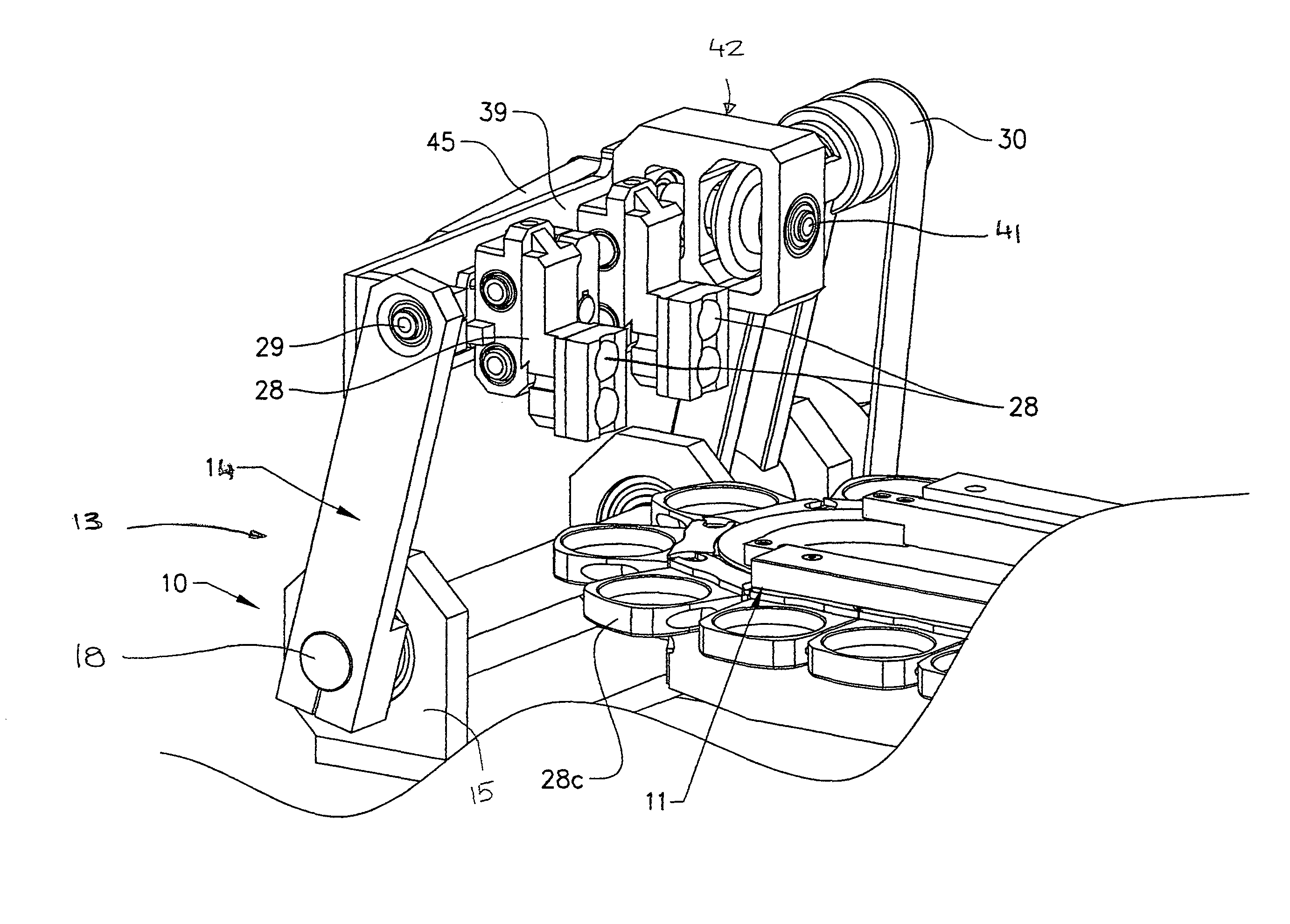
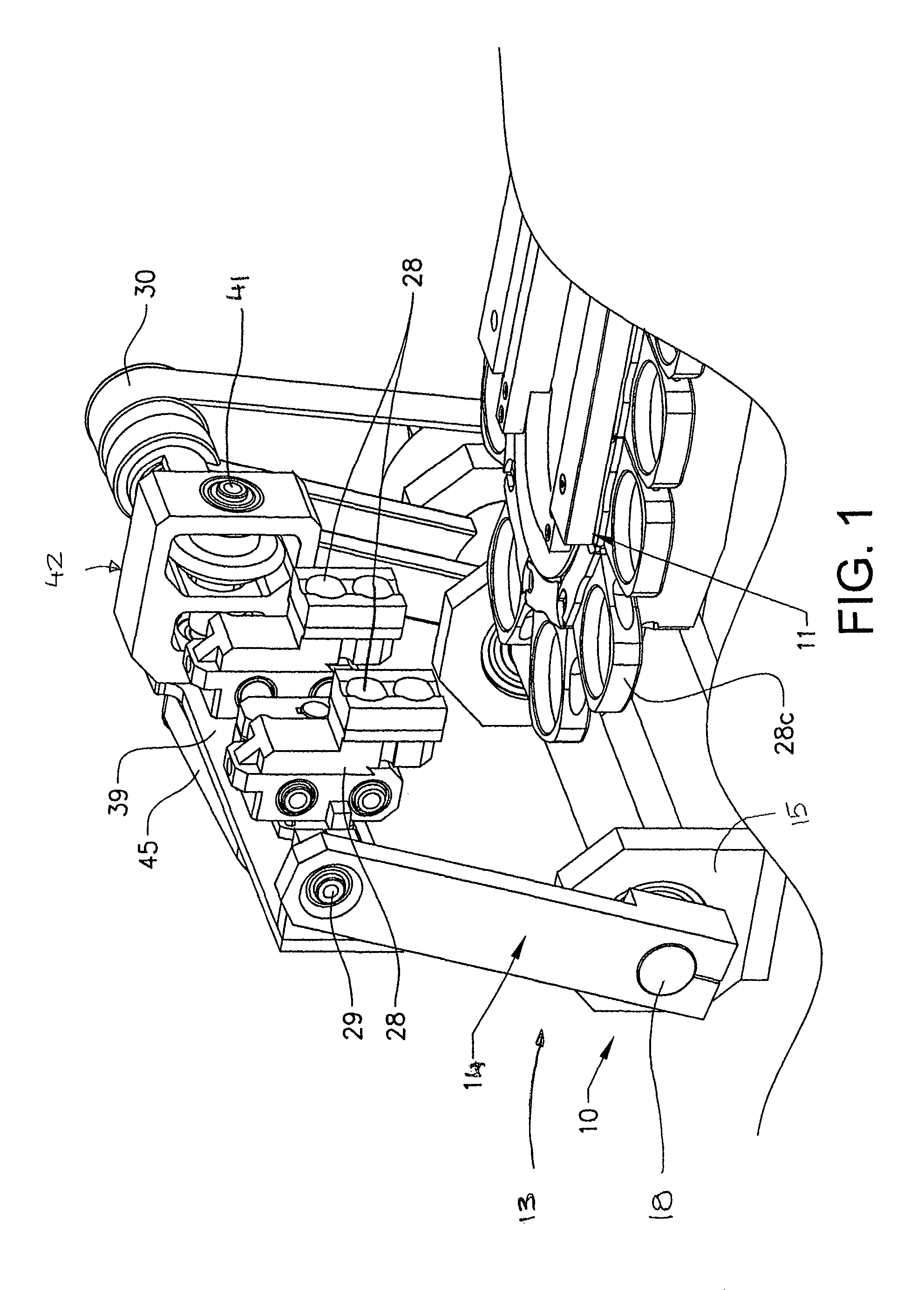
[0086]The above example describes the invention where the frame arrangement 13 is made to perform an accelerating movement about the said vertical axis 17 during its pivoting movement to the container release position. The acceleration is performed so that the speed of the container pickers / placers 28 corresponds to the continuous speed of the second conveyor 12 in the release position. This embodiment is preferably used where the second conveyor is placed with its main direction of transport arranged substantially parallel to the first horizontal axis of the frame arrangement.

second embodiment

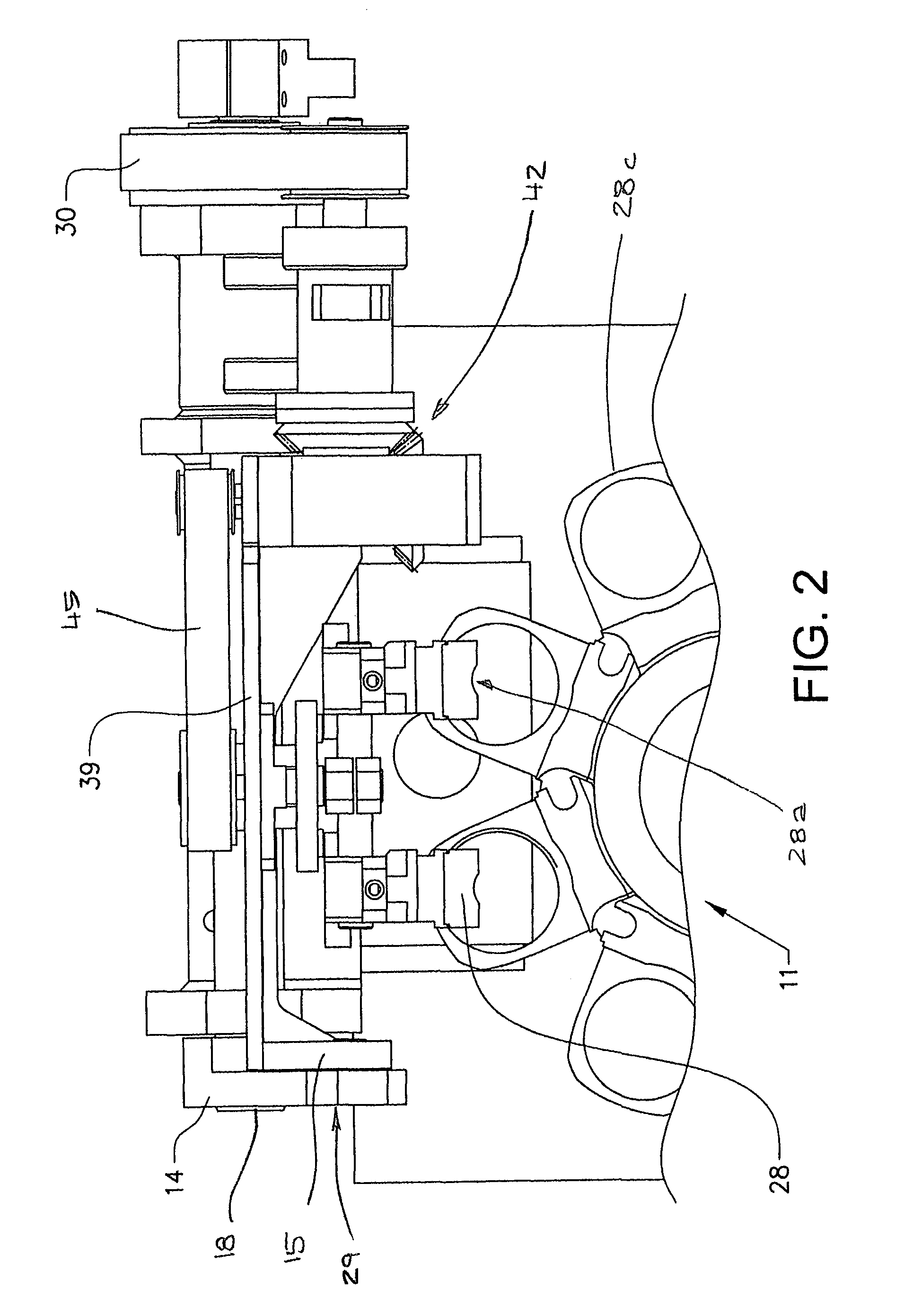
[0087]According to the invention, shown in FIGS. 13-20, the frame arrangement 13 performs a pivoting movement to the container release position about the first, horizontal axis 16. At the same time as this pivoting movement, the tube pickers / placers 28 perform a pivoting movement about the axis 31 and a rotation of the holder supporting the container pickers / placers 28. The holder is rotated a predetermined angle about a shaft arranged at right angles to the axis 31.

[0088]This embodiment is preferably, but not necessarily, used where the second conveyor 50 is placed with its main direction of transport arranged substantially at right angles to the first horizontal axis as shown in FIG. 13.

[0089]The pivoting movement of the frame arrangement 13 is arranged to be controlled in the same way as described in connection with FIG. 4 above, with the exception that the mechanism for rotation about the vertical axis 17 is missing, as shown in FIG. 14.

[0090]FIG. 15 shows a plan view of the pic...


PUM

PropertyMeasurementUnit
angleaaaaaaaaaa
angleaaaaaaaaaa
angle ofaaaaaaaaaa

Abstract

The invention relates to a method for synchronizing, and a transfer device for synchronizing, a movement pattern between two units in a packaging line, wherein one unit is intermittently operated and the second unit is continuously operated. The invention is particularly intended for a transfer device between an intermittently operated filler unit and a continuously operated cartoning machine. The transfer device is provided with a frame (13) arranged to support tube pickers- / placers (28) and is arranged to perform a simultaneous pivoting movement about a first and a second shaft (16, 31), and for rotation about a third shaft (48) at right angles to the second shaft (31). The frame is further provided with means for adjusting the spacing between the tubes and means for compensating for differences in vertical position during the rotating movement in the case where the containers picked from the part circular conveyor of the filling unit.

Description

FIELD OF THE INVENTION[0001]The invention relates to a method and an arrangement for transferring packaging containers, in particular packaging tubes, from a first unit operating intermittently in a first horizontal path to a second unit operating continuously in a second horizontal path.[0002]The invention relates in particular to a method and arrangement for transferring filled tubes from a tube filler, operating in a horizontal circular path and provided with a plurality of filling nozzles, to a continuously operating cartoning machine.PRIOR ART[0003]It has for many years been known to handle packaging containers, and in particular packaging tubes, using the so-called pick-and-place principle. This principle is used, for example, for collecting packaging tubes downstream of a filler, and the principle is applied in such a way that the tubes, downstream of the filler, are placed in a so-called stepped conveyor”, i.e. a belt provided with a number of cases.[0004]To be able to handl...

Claims


Application Information

Patent Timeline
Patent Type & Authority Patents(United States)
IPC IPC(8): B65B35/38B65G47/90B65B35/58B65G47/53
CPCB65B43/52B65B43/46B65B35/243B65G47/904B65G47/915B65B35/36B65B35/38B65B35/56B65B35/58B65G47/53
Inventor NILSSON, JAN
Owner NORDEN MASCH AB
Why Eureka
Try Eureka