
Iron-type golf club head

a golf club head and iron-type technology, applied in the field of iron-type golf club heads, can solve the problems of/her being able to easily make a slice shot, and achieve the effects of reducing the center of gravity, and reducing the impact angl

Active Publication Date: 2012-05-17
SUMITOMO RUBBER IND LTD
View PDF12 Cites 21 Cited by
  • Summary
  • Abstract
  • Description
  • Claims
  • Application Information

AI Technical Summary

Benefits of technology

[0008]The present invention has been devised in light of the above actual circumstances, and a principal object of the present invention is to provide an iron-type golf club head with excellent directional stability of a hit golf ball, basically by providing a bottomed hole part on the lower side of a shaft inserting hole of a head main portion and arranging a heel-side weight member in the bottomed hole part, thereby minimizing an increase in the moment of inertia Ic while making the moment of inertia Ig greater.
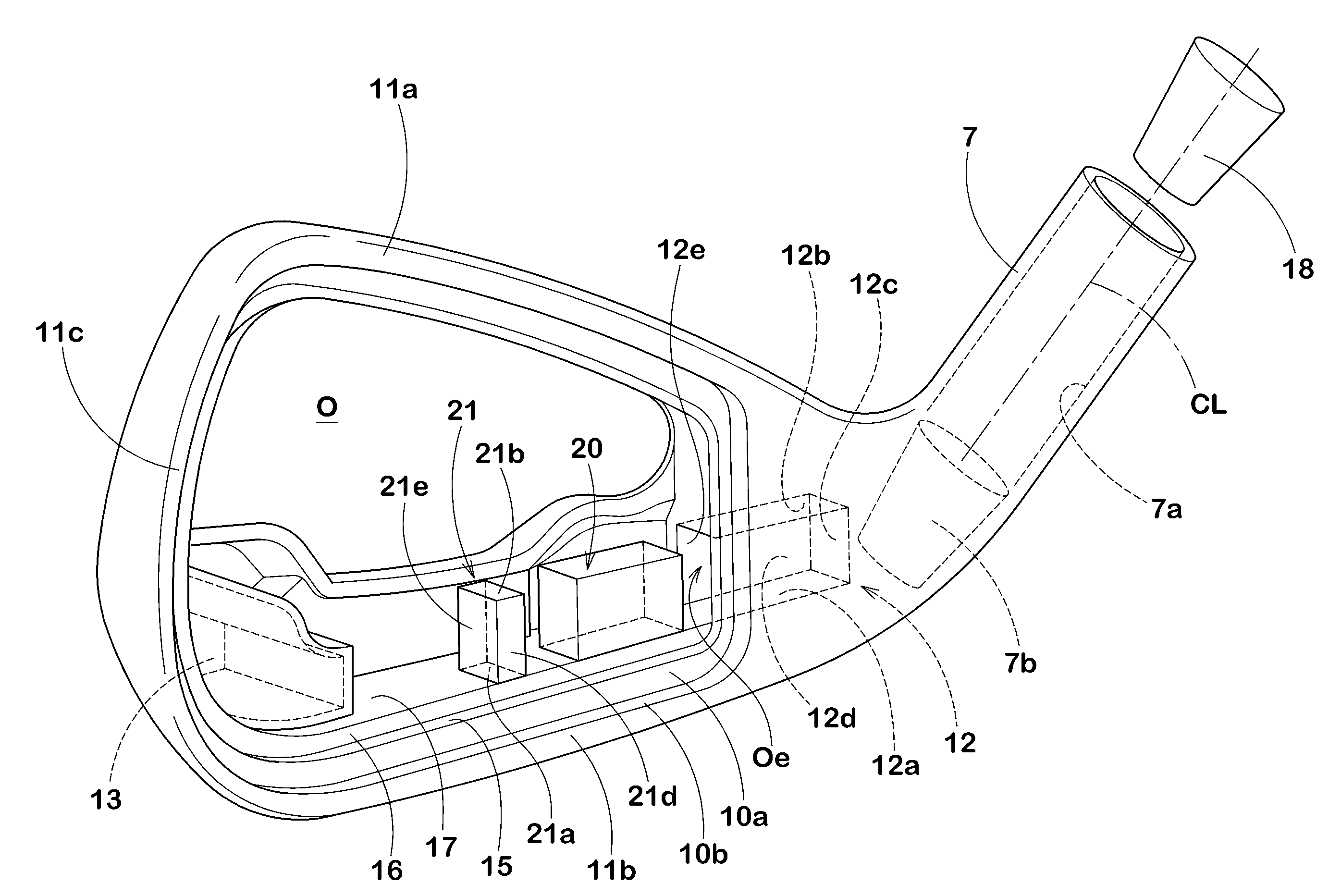
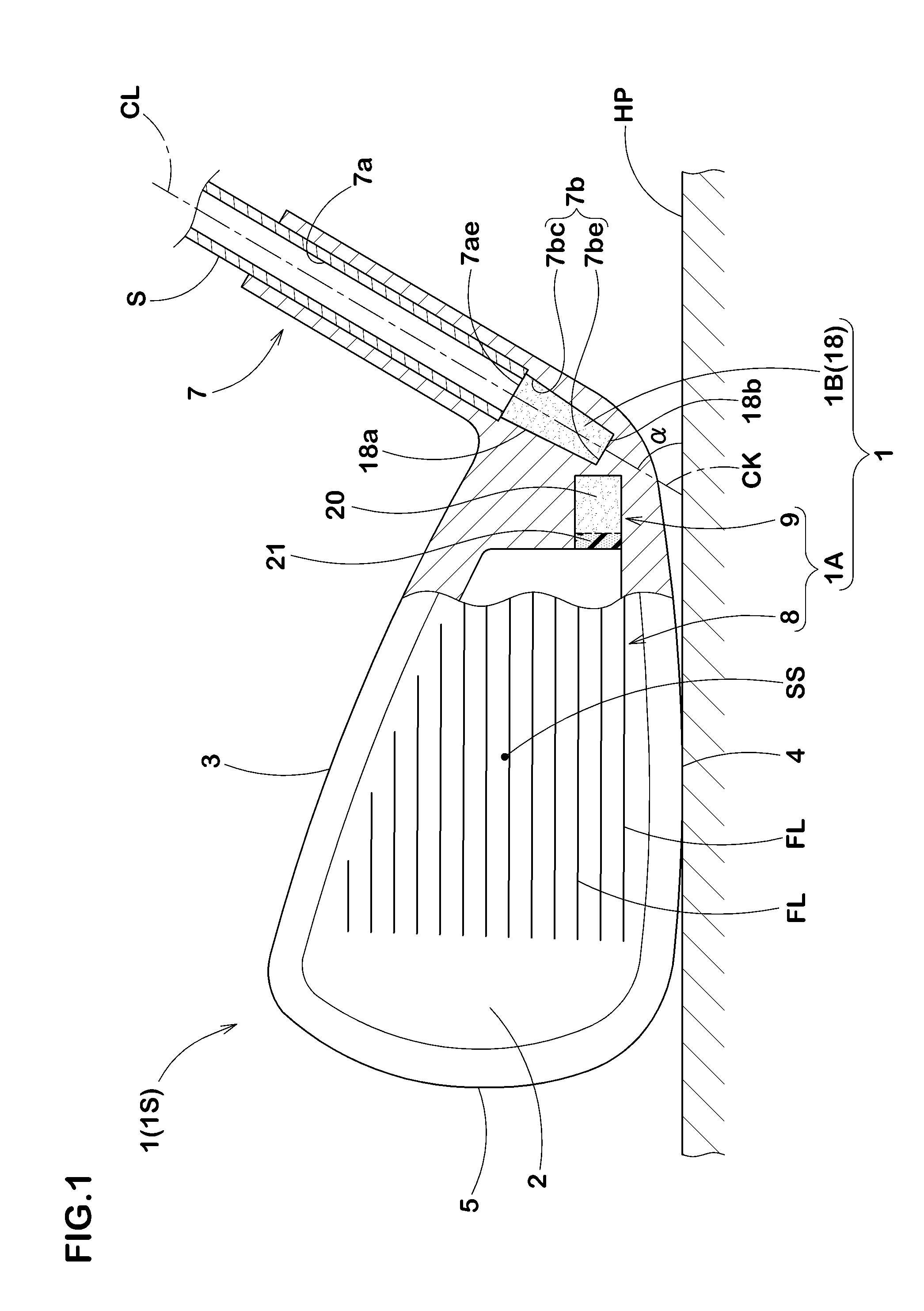
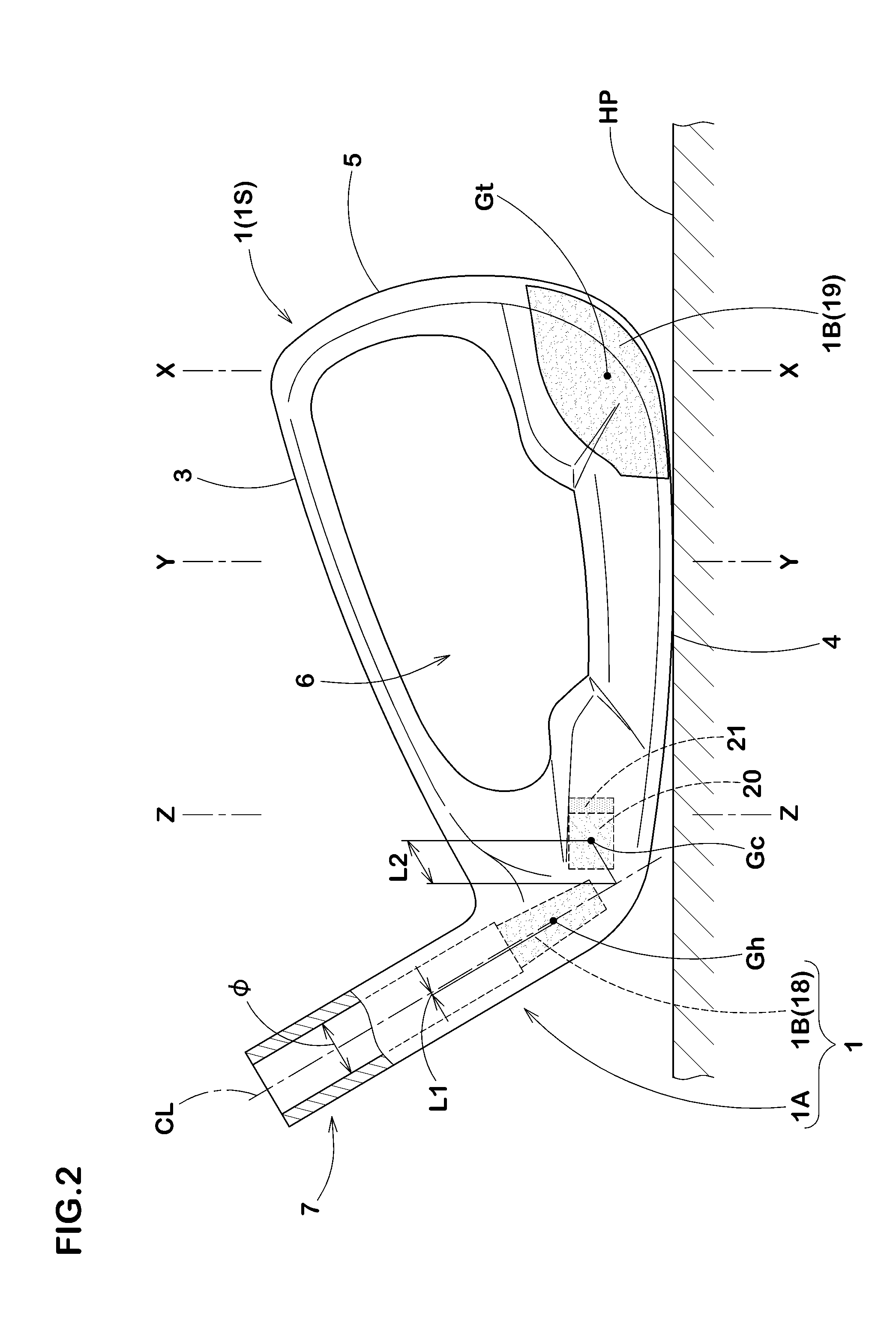
[0014]In the iron-type golf club head of the present invention, a bottomed hole part is provided continuously on the lower side of a shaft inserting hole, and a heel-side weight member is arranged in the bottomed hole part. Thus, great mass can be allocated to a lower part of the heel side of the head. Such an iron-type golf club head can obtain a greater moment of inertia Ig. In addition, since the heel-side weight member is arranged in the lower side of the shaft inserting hole, a shaft axial centerline comes close to a center of gravity of the heel-side weight member. That is to say, any increase in the moment of inertia Ic can be controlled while ensuring the great moment of inertia Ig. Therefore, with the club head of the present invention, when swinging, a golfer can easily return a face to the position at address. In addition, since orientation of the face does not easily change when the golfer mishits a shot, directional stability of a hit golf ball improves. Furthermore, since the heel-side weight member is arranged on the lower side of the head, the golf club has a lower center of gravity. In addition, since the heel-side weight member is arranged in the bottomed hole part which is provided on the lower side of the shaft inserting hole, it does not come off from a head main portion even under action of centrifugal force during a swing. Furthermore, since the bottomed hole part is continuously provided in the shaft inserting hole, the golf club head has good workability and is excellent in productivity.

Problems solved by technology

Such a golf club head a having the great moment of inertia Ic originally had a problem that when a golfer swung it, the face did not fully return to the position at address, thus causing him / her to easily make a slice shot.

Method used


Image

  • Iron-type golf club head
  • Iron-type golf club head
  • Iron-type golf club head

Examples


example

[0088]In order to ensure the effect of the present invention, iron-type golf club heads having a basic configuration as shown in FIG. 1 to FIG. 4 and based on the specification in Table 1 were prototyped and various kinds of actual hitting tests were conducted on them. Each of the heads was molded by bonding, with an adhesive and through caulking, a face receiving frame portion attached to a tubular portion formed of a casting which was made by molding SUS630 (specific gravity: 7.78) with the lost-wax precision casting method, and a face plate (specific gravity: 4.5) which is a pressed mold of Ti-6A1-4V. In addition, a head main portion was manufactured so that a center of gravity position of the head main body does not change if a position and mass of a hollow portion, a heel-side weight member, and an intermediate weight member are varied. In addition, a position to fixedly set up a bottomed hole part is provided at a same position of each head, and a position to fixedly set up a ...


PUM


Abstract

An iron-type golf club head comprises a head main portion having a face for hitting a golf ball, and weight members made of metallic material having heavier specific gravity than the head main portion. The head main portion has a tubular portion provided on a heel side of the face and having a shaft inserting hole. The tubular portion is provided continuously on the lower side of the shaft inserting hole with a bottomed hole part for arranging the weight members. The weight members include a heel-side weight member disposed in the bottomed hole part.

Description

BACKGROUND OF THE INVENTION[0001]1. Field of the Invention[0002]The present invention relates to an iron-type golf club head having improved directional stability of a hit golf ball.[0003]2. Description of the Background Art[0004]In recent years, an iron-type golf club head a position of whose center of gravity was improved by bonding more than two kinds of different metallic materials has been proposed. FIG. 10 shows one example of such an iron-type gold club head a. The club head a includes a main portion b, and weight members ct, ch having heavier specific gravity than the main portion b, the weight members ct, ch being respectively arranged in a lower part of a toe portion t and a heel portion h on a rear of a face portion of the main portion b. In this type of club head a, great mass is allocated to a toe side and a heel side of a face portion. Hence, a moment of inertia around a vertical axis passing through the center of gravity of the head G (which may be hereinafter referre...

Claims


Application Information

Patent Timeline
Patent Type & Authority Applications(United States)
IPC IPC(8): A63B53/04A63B53/06A63B102/32
CPCA63B53/047A63B53/0475A63B59/0092A63B2053/0408A63B2053/0491A63B2053/0416A63B2053/0433A63B60/02A63B60/54A63B53/0408A63B53/0416A63B53/0433
Inventor YAMAMOTO, AKIO
Owner SUMITOMO RUBBER IND LTD
Learn More