Airbag

a technology of airbags and airbags, applied in the field of airbags, can solve the problems of airbags sometimes failing to inflate smoothly, irregular contour of airbags, and temporary joints that cannot be located in such locations, so as to reduce the thickness of airbags, reduce the outer diameter, and ensure the effect of safety

Inactive Publication Date: 2013-04-09
TOYODA GOSEI CO LTD
View PDF14 Cites 10 Cited by
  • Summary
  • Abstract
  • Description
  • Claims
  • Application Information

AI Technical Summary

Benefits of technology

[0014]In the airbag thus configured, the temporary joint is formed by joining the opposing walls together in an area of the tuck that is formed by tucking a part of the outer circumferential wall toward an interior of the airbag. With this configuration, when the airbag inflates with a suppressed volume with the temporary joint kept jointed, the temporary joint does not appear on the outer surface of the airbag. Further, the temporary joint extends toward the turn-round region that forms the bottom of the tuck and has the first end proximate the outermost ends near the outer surface of the airbag and the second end in the vicinity of the turn-round region. Accordingly, when the airbag inflates with a suppressed volume, the outer circumferential wall of the airbag stays smooth even in areas where the tuck and temporary joint are located as well as the temporary joint hardly appears on the outer surface of the airbag. Therefore, there is no problem in locating the temporary joint on such an area of the airbag as to be contactable with an occupant.
[0024]In the above configuration, if the tuck and temporary joint are formed on both of the vehicle body side wall and occupant side wall, the airbag will be assuredly prevented from inflating into an irregular shape when inflated with the temporary joints kept jointed, since both of the occupant side wall and vehicle body side wall are reduced in length of the outer circumference slightly, and the difference in volume of the airbag between before and after disjointing of the temporary joints will be increased.

Problems solved by technology

However, since the tucked region in the conventional airbag is formed to protrude outwardly from the airbag, when the airbag is inflated with a suppressed volume while the temporary joint is kept jointed, the tucked region protrudes partially on the outer surface of the airbag, thereby making the contour of the airbag of suppressed volume irregular.
Moreover, since the tucked region is likely to be caught by a housing of the airbag or a surrounding member, the airbag sometimes fails to inflate smoothly.
Further, the temporary joint cannot be located on such a location as to contact with an occupant upon deployment since it is formed in a projecting fashion on the outer surface of the airbag.
However, with this configuration, rupture or raveling of the temporary joint propagates to two directions since the temporary joint is bifurcate starting the angular portion, and therefore, raveling or rupture of the sewing thread occurs on more than one region proximate to each other.

Method used


Image

  • Airbag
  • Airbag
  • Airbag

Examples


Embodiment Construction

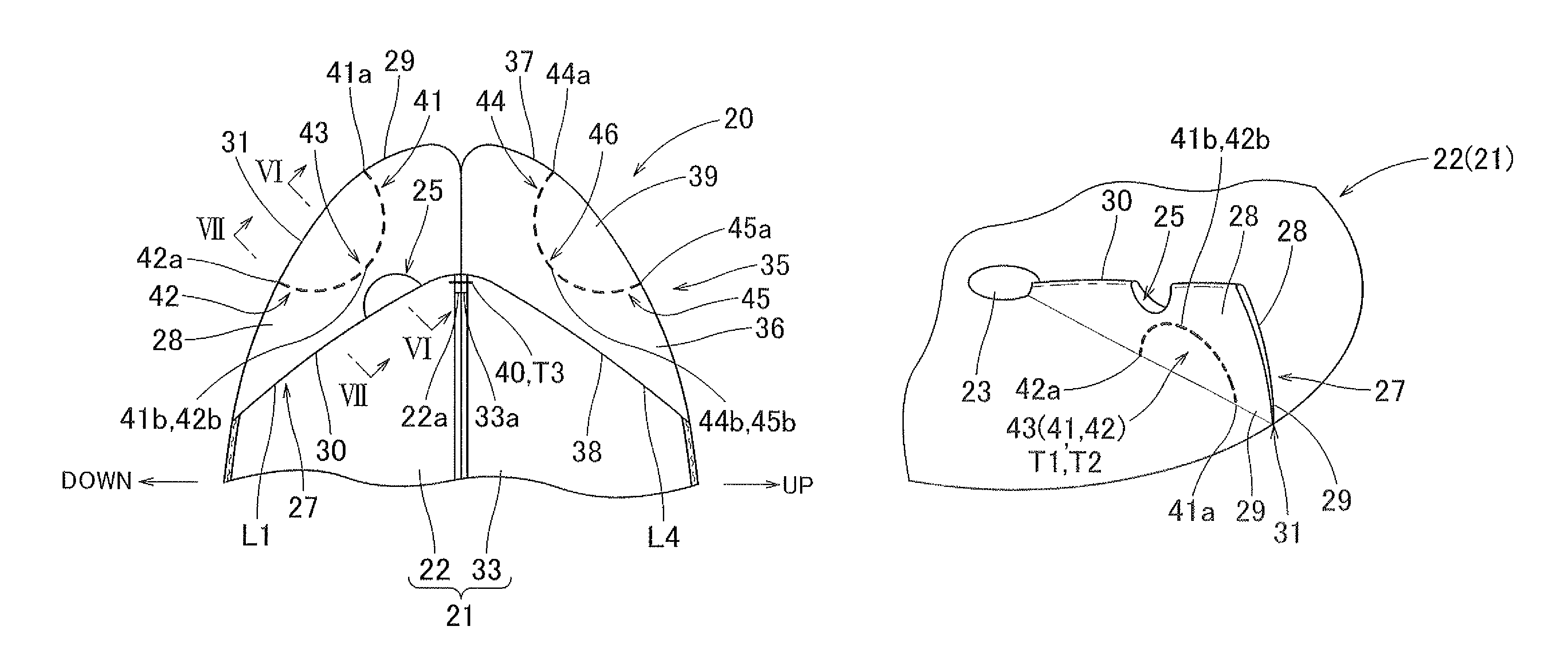
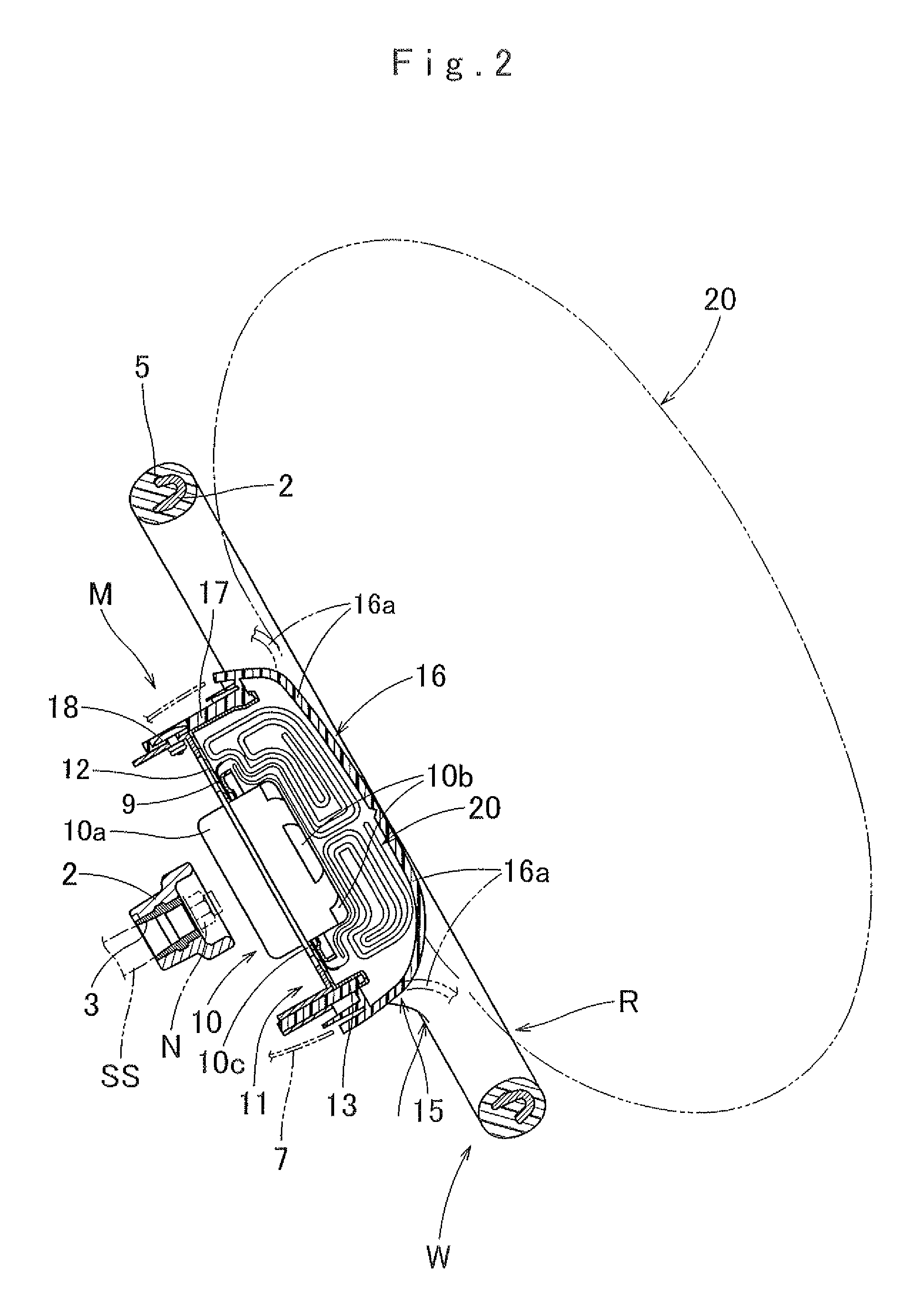
[0044]Preferred embodiments of the present invention are described below with reference to the accompanying drawings. In the preferred embodiments, the invention is described as applied to an airbag 20 for use in an airbag apparatus M mountable on a steering wheel. However, the invention is not limited to the embodiments disclosed herein. All modifications within the appended claims and equivalents relative thereto are intended to be encompassed in the scope of the claims.

[0045]Unless otherwise specified, front / rear, up / down, and left / right directions in the embodiments are based on a steering wheel W mounted on a vehicle and steered straight ahead. Specifically, up / down direction is intended to refer to an up / down direction extending along an axial direction of a steering shaft SS (FIG. 2) on which the steering wheel W is mounted. Front / rear direction is intended to refer to a front / rear direction of a vehicle extending orthogonal to the axial direction of the steering shaft SS, an...


PUM


Abstract

An airbag includes a tuck that is formed by tucking a part of the outer circumferential wall toward an interior of the airbag. The tuck includes two opposing walls, a turn-round region that forms a bottom of the tuck and outermost ends of the opposing walls adjacent to and continuing to an outer surface of the airbag. The airbag further includes a temporary joint that joins the opposing walls of the tuck together in such a manner as to disjoint when an inner pressure of the airbag at inflation is increased. The temporary joint is formed into such a line that extends toward the turn-round region and has a first end proximate the outermost ends and a second end in the vicinity of the turn-round region.

Description

[0001]The present application claims priority from Japanese Patent Application No. 2010-77556 of Naganawa et al., filed on Mar. 30, 2010, the disclosure of which is hereby incorporated into the present application by reference.BACKGROUND OF THE INVENTION[0002]1. Field of the Invention[0003]The present invention relates to an airbag which includes an outer circumferential wall comprised of flexible sheet material, and is housed in a housing in a folded-up state and inflatable with inflation gas for emergence from the housing and deployment.[0004]2. Description of Related Art[0005]JP 7-205738 A discloses an airbag that includes on the outer circumferential wall a vent hole and a temporary joint which is formed by tucking a part of the outer circumferential wall encompassing the vent hole and sewing the tucked region with a sewing thread in such a manner as to close off the vent hole. With such a temporary joint, the airbag inflates with a suppressed volume in an initial stage of infla...

Claims


Application Information

Patent Timeline
Patent Type & Authority Patents(United States)
IPC IPC(8): B60R21/239B60R21/2342
CPCB60R21/203B60R21/2342B60R21/239
Inventor NAGANAWA, AKITOSHIISHIGURO, NAOHIKO
Owner TOYODA GOSEI CO LTD
Why Eureka
Try Eureka