

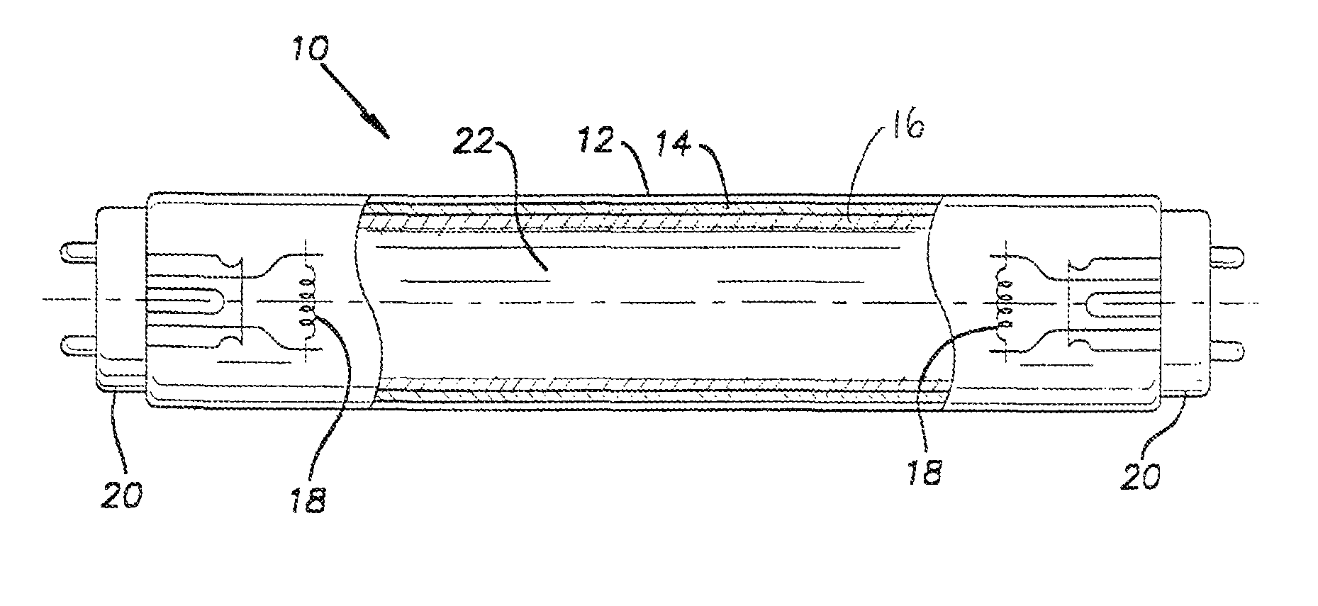
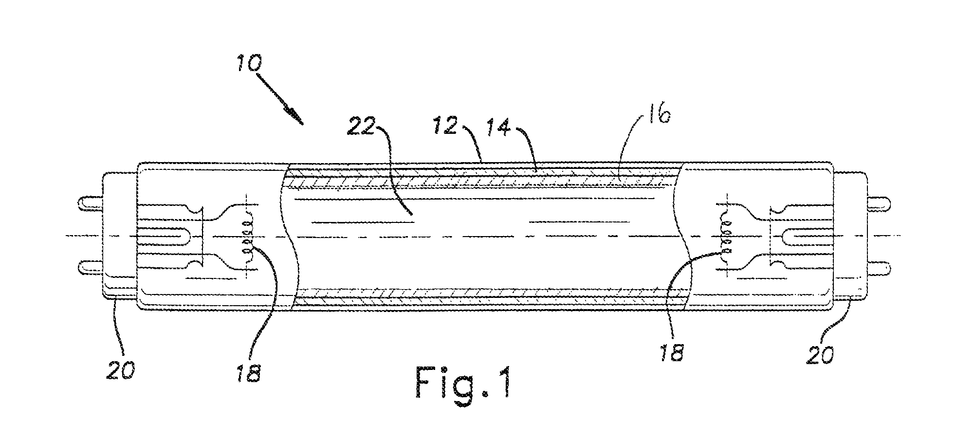
Fluorescent lamp with underlying yttrium vanadate phosphor layer and protective phosphor layer
a technology of phosphor layer and fluorescent lamp, which is applied in the direction of discharge tube/lamp details, discharge tube luminescnet screen, low-pressure discharge lamp, etc., can solve the problems of reducing the overall efficiency of the lamp, reducing the phosphor conversion efficiency and lumen output of the lamp over its life cycle, and most of the 185 nm wavelength radiation wasted
- Summary
- Abstract
- Description
- Claims
- Application Information
AI Technical Summary
Problems solved by technology
Method used
Image


Examples
example 1
[0024]Five T8 lamps with glass envelopes each having a surface area of 972.88 cm2, a diameter of 25.4 mm and a length of 1219.2 mm were coated with an underlying layer followed by a protective layer each having the following phosphor weight percentage compositions shown in Table 1 and made following the method in the Detailed Description. Each lamp was filled with argon at a fill pressure in the range of 2.0 to 3.5 ton and a dose of mercury in the range of 2.0 to 4.0 mg. The color points of each of the phosphor layers are provided.
[0025]
TABLE 1protective layerYEO61.9%LAP28.7%SECA 9.6%CCX0.4122CCY0.3931underlying layerYttrium41.9%VanadateLAP42.9%SECA15.2%CCX0.4068CCY0.4070
[0026]The yttrium vanadate phosphor that was used was yttrium vanadate phosphate Y(P,V)O4: Eu3+.
[0027]Each of the layers was coated on the lamps according to the following surface densities in the unit of mg / cm2 and to have the following ratio of coating surface densities shown in Table 2. Lamps of cell B had no pro...
example 2
[0033]The same lamps described above in Example 1 having the same surface density, protective layer / underlying layer surface density ratio, and phosphor compositions were used to produce 500 hour lamp data.
[0034]The percentage of the lumens maintained at 500 hours compared to the lumens at 100 hours on the y axis (“lumen maintenance”) was plotted as a function of the protective layer / underlying layer surface density ratio (“surface density ratio”) in FIG. 3. This figure shows that the lumen percentage maintained was at least about 97.5% at a surface density ratio of about 0.2, which is greater than the 95.5% highest lumen % maintained at a surface density ratio of 0 with no protective layer. This shows the effectiveness of the protective layer. The surface density ratios of about 0.5 and about 1.0 produced even better % lumen maintenance of at least about 98.0.
[0035]Lamp cells C and D of the invention, which had an average surface density ratio of about 0.50 and about 1.00 favorably...
PUM
 Abstract
Description
Claims
Application Information