Sports ring receiver and transmitting unit

a technology of transmitting unit and ring receiver, which is applied in the field of electronic communication devices, can solve problems such as unknown unification methods, and achieve the effect of enhancing the experience of fans and enhancing the unity

Inactive Publication Date: 2013-04-16
HERMANN II GROVER M
View PDF7 Cites 9 Cited by
  • Summary
  • Abstract
  • Description
  • Claims
  • Application Information

AI Technical Summary

Benefits of technology

[0011]The invention addresses the functions needed to bring awareness to the offensive and / or defensive play on the field or court of play after the play occurs. The rings can be worn by the sports fans to provide an instant feedback device that ideally highlights a thrilling offensive and / or defensive play on the field or court after the occurrence of the play on said field or court for either the away or home team. This unifies the fans of each team with one another, and also provides immediate information about how each fan's team is doing on the field or court. This intensifies the experience of the fans and gives a greater sense of unity to fans and intimacy with play.

Problems solved by technology

However, during a live and in-person sports event, there is no known means for unifying the fans who support each team and giving them “instant feedback” regarding the play in the field or court.

Method used


Image

  • Sports ring receiver and transmitting unit
  • Sports ring receiver and transmitting unit
  • Sports ring receiver and transmitting unit

Examples


Embodiment Construction

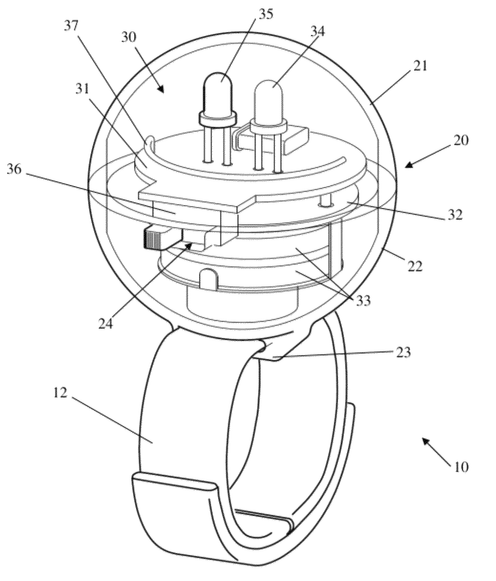
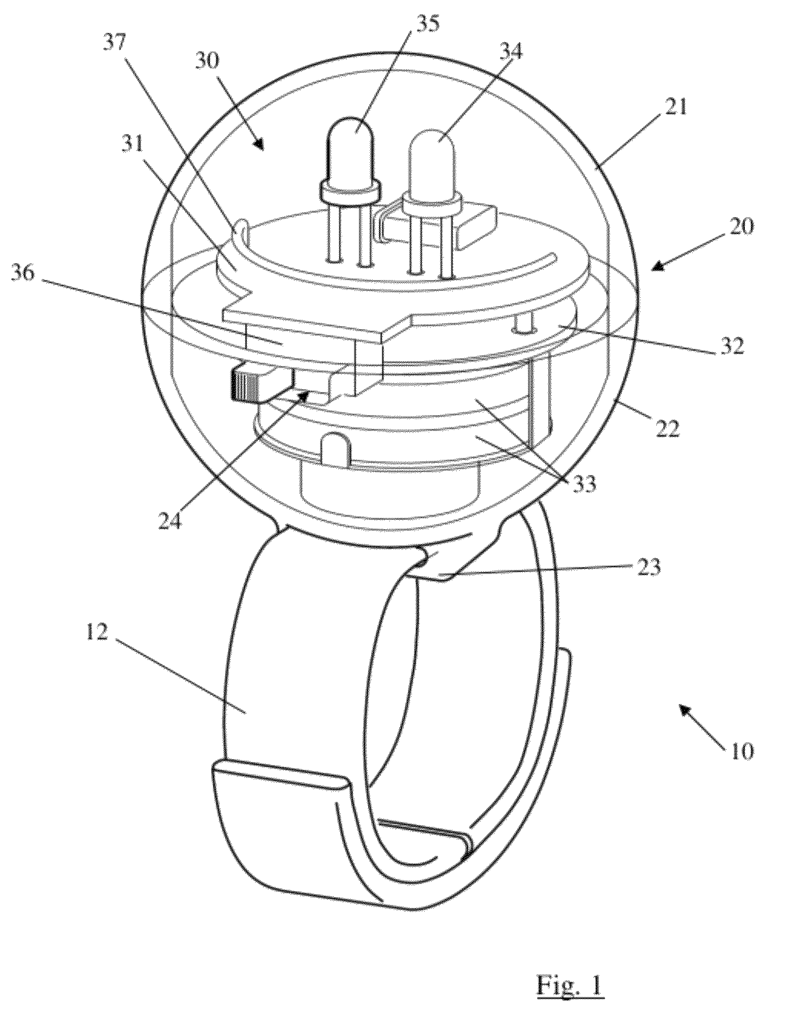
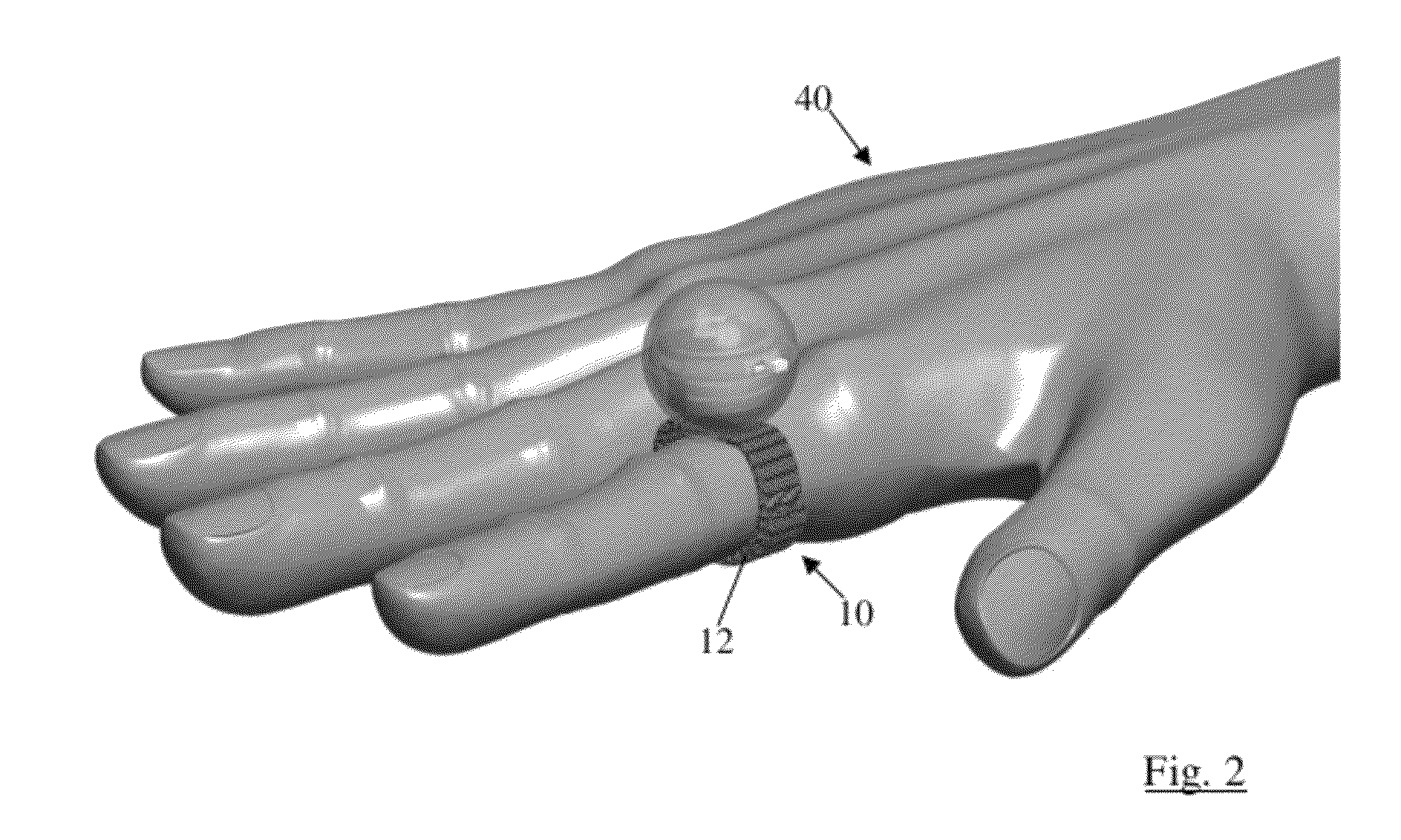
[0017]The preferred ring 10 of the present invention is shown in FIG. 1 having a band 12, a globe 20 and electronics 30 within the globe 20. The band 12 is preferably a flexible material, including, but not limited to fabric, leather, a metal band with interlocking links to permit relative movement, or another flexible material. One exemplary material for the band 12 is hooks and loops material such as that sold under the trademark VELCRO. In operation, such material allows for variability in the size of the wearer's finger, and permits easy removability while still securing the ring well on the finger. Of course, the band 12 could be made large enough to be worn on the wearer's wrist, ankle, neck or any other part of the wearer's body or apparel without affecting the operation of the remainder of the ring 10.

[0018]The globe 20 is preferably a translucent sphere made up of an upper hemisphere 21 and a lower hemisphere 22. The terms “upper” and “lower” refer to the relative positions...


PUM


Abstract

A ring has a sphere on a band and is worn on the finger of a sports fan. An electrical circuit includes a power source and two LEDs. An antenna allows the ring circuit to receive signals sent wirelessly. A three position switch changes the settings of the circuit. When the switch is in a middle position, the ring is disconnected from its power source. When the switch is in one or the other of the other two positions, the wireless receiver components can receive signals from a transmitting unit. The ring is preferably worn by a sports fan at a sporting event, and upon switching the switch to the position associated with the team the fan supports, the ring can receive signals. Signals will be transmitted from the transmitting unit, and will cause the ring to flash the LED. Rings worn by fans flash in support of the fans' team.

Description

CROSS-REFERENCES TO RELATED APPLICATIONS[0001]This application is a continuation-in-part of U.S. Design patent application Ser. No. 29 / 382,944 filed Jan. 10, 2011. The above prior application is hereby incorporated by reference.STATEMENT REGARDING FEDERALLY-SPONSORED RESEARCH AND DEVELOPMENT[0002](Not Applicable)REFERENCE TO AN APPENDIX[0003](Not Applicable)BACKGROUND OF THE INVENTION[0004]This invention pertains to the field of electronic communication devices used by attendees of sports events.[0005]It is known that people who attend live sports contests can merely observe the game or match and have no interaction with the athletes who might be competing a mere few feet or many hundreds of feet away. However, because a sports contest is typically observed mostly by people who enthusiastically respond to every triumph and mistake of both teams, the attendees of sports contests normally make efforts to interact with the contest by indicating their approval or disapproval of action o...

Claims


Application Information

Patent Timeline
Patent Type & Authority Patents(United States)
IPC IPC(8): F21V21/08G06F3/033
CPCG08B5/36A44C9/00A44C15/0015
Inventor HERMANN, II, GROVER M.
Owner HERMANN II GROVER M
Why Eureka
Try Eureka