Journal air bearing

a technology of air bearings and bearings, applied in the direction of bearings, shafts and bearings, rotary bearings, etc., can solve problems such as destabilization of components, and achieve the effect of reducing fluid pressure build-up

Active Publication Date: 2013-04-16
HAMILTON SUNDSTRAND CORP
View PDF14 Cites 23 Cited by
  • Summary
  • Abstract
  • Description
  • Claims
  • Application Information

AI Technical Summary

Benefits of technology

[0005]An example journal air bearing foil arrangement includes a top foil having an inner surface configured to face a rotating shaft and an intermediate foil configured to be biased radially inboard toward an outer surface of the

Problems solved by technology

The varied pressures can

Method used


Image

  • Journal air bearing
  • Journal air bearing
  • Journal air bearing

Examples


Embodiment Construction

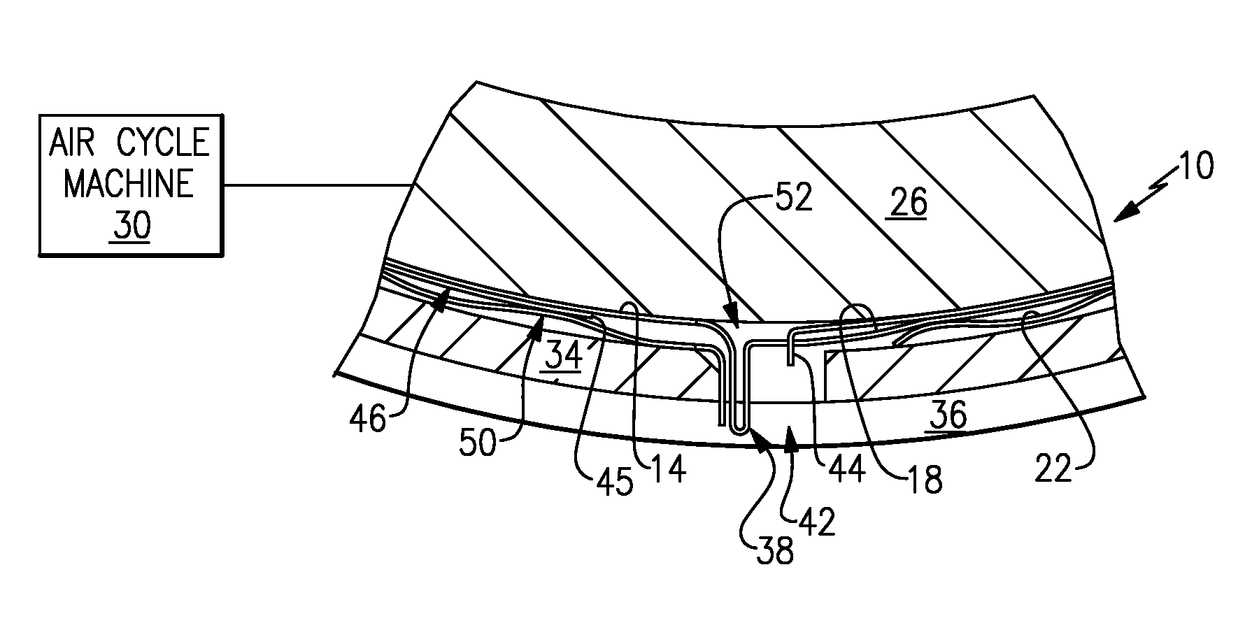
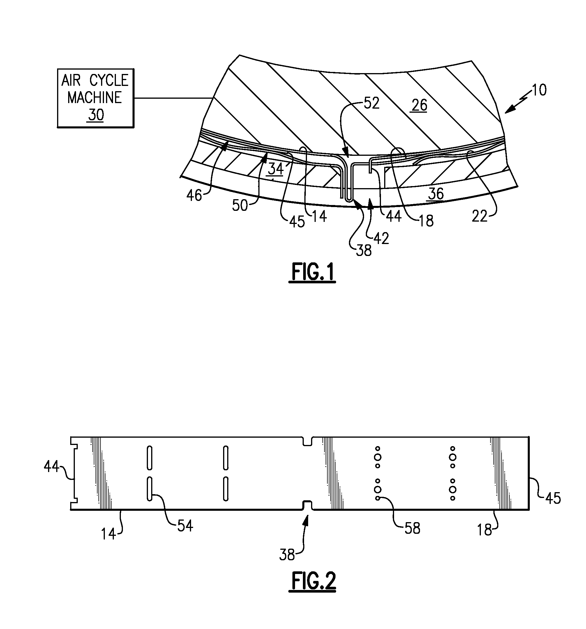
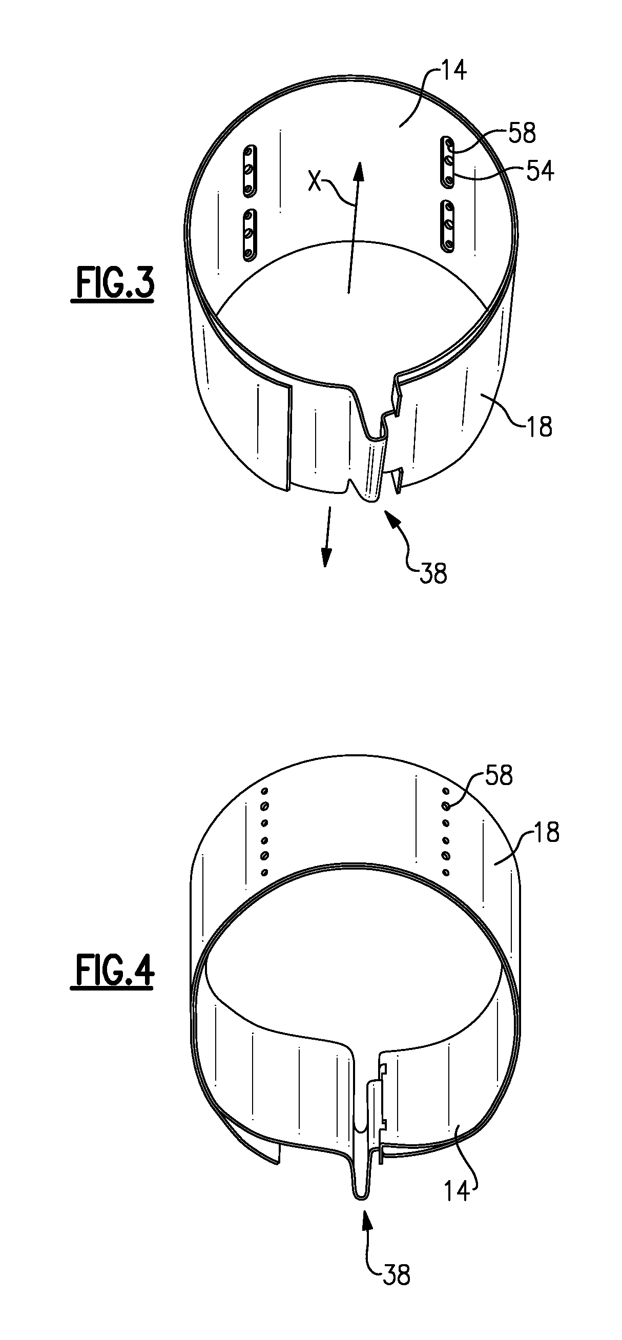
[0014]Referring to FIG. 1, an example journal air bearing arrangement 10 includes a top foil 14, an intermediate foil 18, and a bump foil 22. The example journal air bearing arrangement 10 rotatably supports a shaft 26 of an air cycle machine 30 in other examples the journal air bearings are used within other aircraft accessories such as turbo-compressors, cabin air compressors, or ram air fans.

[0015]The arrangement 10 and the shaft 26 are received within a journal sleeve 34. A formed key 38 extends radially relative to the shaft 26. The formed key 38 is received within a slot 42 defined within the journal sleeve 34, which is received within a housing bore 36. O-rings are used to retain the journal sleeve 34 within the housing bore 36. When the shaft 26 rotates, the formed key 38 contacts the slot 42, which prevents the bearing arrangement 10 from rotating with the shaft 26.

[0016]In this example, the top foil 14 and the intermediate foil 18 are a single piece having a first end port...


PUM

PropertyMeasurementUnit
Angleaaaaaaaaaa
Timeaaaaaaaaaa
Solid angleaaaaaaaaaa

Abstract

An example journal air bearing for a rotatable shaft of an air cycle machine includes a top foil configured to receive a rotatable shaft, and an intermediate foil radially outboard the top foil. A journal sleeve is radially outboard the intermediate foil. The top foil and the intermediate foil establish apertures configured to communicate fluid between a first position radially inboard the top foil and a second position radially outboard the intermediate foil.

Description

BACKGROUND[0001]This disclosure relates generally to journal air bearings, which are also known as hydrodynamic fluid film journal bearings or foil bearings.[0002]As known, journal air bearings support rotatable components, such as a shaft within an air cycle machine of an aircraft. A typical journal air bearing arrangement includes a top foil, an intermediate foil, and a bump foil. The foils are received within a journal sleeves and wrapped around a rotatable component. The top foil is closer to the rotatable component than the other foils. Journal air bearings use a fluid, such as air, to support the component during rotation. There is little or no contact between the top foil and the rotatable component when the component rotates.[0003]Some journal air bearings include a formed key that extends radially relative to the axis of rotation of the component. The formed key is received within a slot in the journal sleeve. The formed key contacts the edges of the slot to limit rotation ...

Claims


Application Information

Patent Timeline
IPC IPC(8): F16C32/06
CPCF16C17/024Y10T29/49696F16C43/02
Inventor MCAULIFFE, CHRISTOPHERSTRUZIAK, RONALD M.
Owner HAMILTON SUNDSTRAND CORP
Why Eureka
Try Eureka