Intercooled cooled cooling integrated air cycle machine

a technology of air cycle machine and cooling air, which is applied in the direction of machines/engines, efficient propulsion technologies, transportation and packaging, etc., can solve the problem that conventional cooling air methods cannot provide cooling air at sufficient pressur

Active Publication Date: 2018-05-10
RTX CORP
View PDF8 Cites 13 Cited by
  • Summary
  • Abstract
  • Description
  • Claims
  • Application Information

AI Technical Summary

Benefits of technology

[0021]In accordance with another embodiment or any of the gas turbine engine embodiments above, the generator can provide electricity based on the pneumatic power to one or more of an electric heater, an auxiliary system, a motor drive, and an aircraft system.
[0022]In accordance with one or more embodiments, a method of providing bleed air to an air cycle machine is provided. The method comprises cooling a bleed air flow in the first cooling stage to produce a cooled bleed air flow; increasing a pressure of the cooled bleed air flow in the pump to produce a pressurized cooled bleed air flow; cooling the pressurized cooled bleed air flow in the first second exchanger to produce an intercooled cooling air; and selectively receiving at least a portion of the cool bleed air or at least a portion of the intercooled cooling air by the air cycle machine that is in fluid communication with outputs of the first and second cooling stages.

Problems solved by technology

That is, conventional cooling air methods fail to provide cooling air at sufficient pressure to be introduced to the highest pressure places of the gas turbine engine and at cool enough temperature to reduce key component temperatures.

Method used


Image

  • Intercooled cooled cooling integrated air cycle machine
  • Intercooled cooled cooling integrated air cycle machine
  • Intercooled cooled cooling integrated air cycle machine

Examples


Embodiment Construction

[0029]A detailed description of one or more embodiments of the disclosed apparatus and method are presented herein by way of exemplification and not limitation with reference to the Figures.

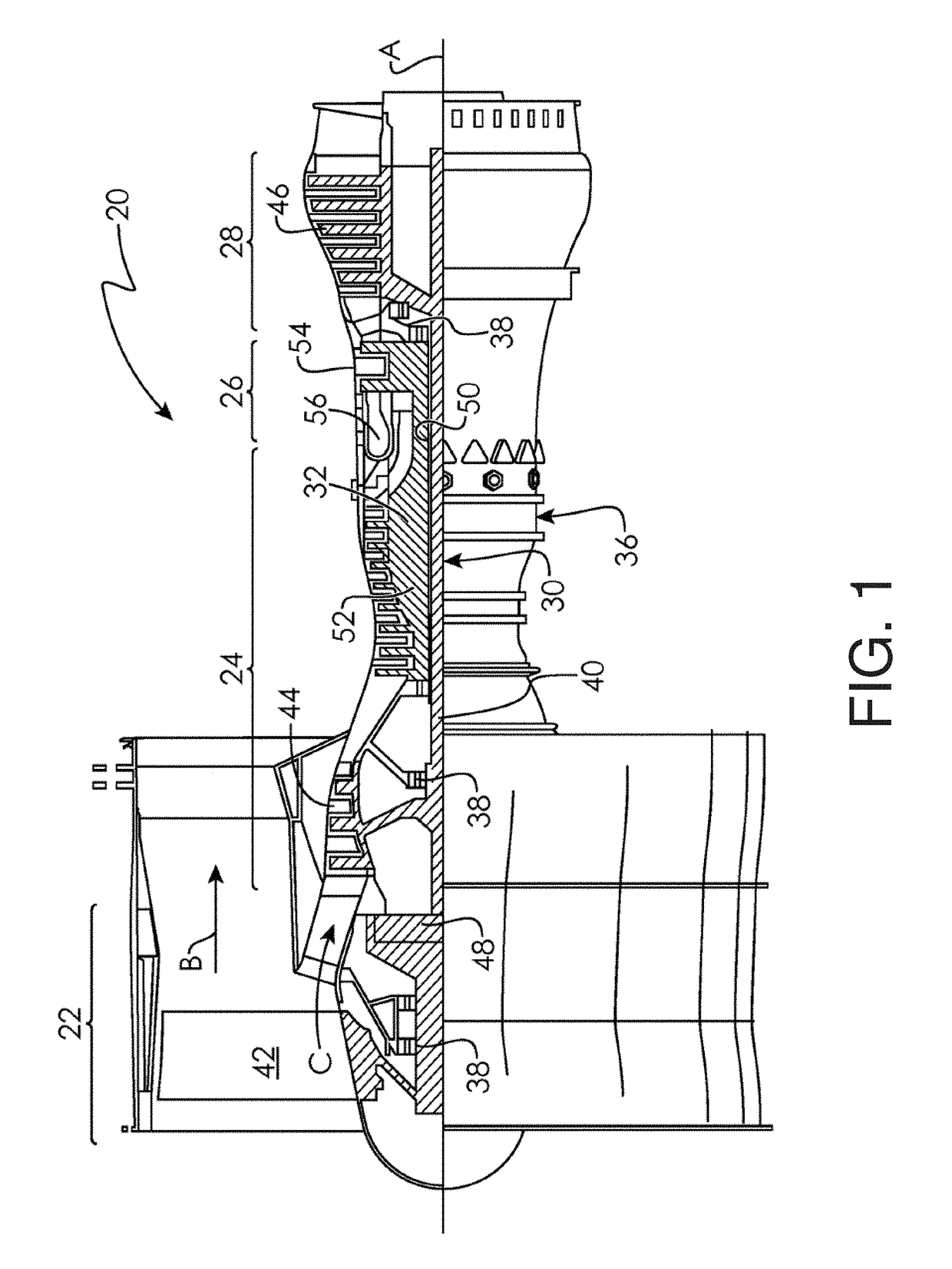
[0030]FIG. 1 schematically illustrates a gas turbine engine 20. The gas turbine engine 20 is disclosed herein as a two-spool turbofan that generally incorporates a fan section 22, a compressor section 24, a combustor section 26 and a turbine section 28. Alternative engines might include an augmenter section (not shown) among other systems or features. The fan section 22 drives air along a bypass flow path B in a bypass duct, while the compressor section 24 drives air along a core flow path C for compression and communication into the combustor section 26 then expansion through the turbine section 28. Although depicted as a two-spool turbofan gas turbine engine in the disclosed non-limiting embodiment, it should be understood that the concepts described herein are not limited to use with two-spool...


PUM


Abstract

An intercooled cooling system for a gas turbine engine is provided. The intercooled cooling system includes cooling stages in fluid communication with an air stream utilized for cooling. A first cooling stage is fluidly coupled to a bleed port of the gas turbine engine to receive and cool bleed air with the air stream to produce a cool bleed air. The intercooled cooling system includes a pump fluidly coupled to the first cooling stage to receive and increase a pressure of the cool bleed air to produce a pressurized cool bleed air. A second cooling stage is fluidly coupled to the pump to receive and cool the pressurized cool bleed air to produce an intercooled cooling air. The intercooled cooling system includes an air cycle machine in fluid communication to outputs of the cooling stages to selectively receive the cool bleed air or the intercooled cooling air.

Description

BACKGROUND[0001]This present disclosure relates to a gas turbine engine, and more particularly to improvements in providing cooling air from a compressor section to a turbine section in a gas turbine engine.[0002]Gas turbine engines are known and typically include a fan delivering air into a bypass duct as propulsion air. Further, the fan delivers air into a compressor section where it is compressed. The compressed air passes into a combustion section where it is mixed with fuel and ignited. Products of this combustion pass downstream over turbine rotors driving them to rotate.[0003]It is known to provide cooling air from the compressor to the turbine section to lower the operating temperatures in the turbine section and improve overall engine operation. Typically, air from the high compressor discharge has been tapped, passed through a heat exchanger, which may sit in the bypass duct and then delivered into the turbine section. The air from the downstream most end of the compressor...

Claims


Application Information

Patent Timeline
Patent Type & Authority Applications(United States)
IPC IPC(8): F02C7/143F02C7/18
CPCF02C7/143F05D2260/211F02C7/185B64D13/06F02K3/115F02C6/08F02C7/141Y02T50/60F05D2260/213
Inventor STAUBACH, JOSEPH B.SNAPE, NATHAN
Owner RTX CORP
Why Eureka
Try Eureka