Air cycle machine for an aircraft environmental control system

a technology of environmental control system and air cycle machine, which is applied in the direction of lighting and heating apparatus, domestic cooling apparatus, energy-efficient board measures, etc., can solve the problems of relatively large packaging space and relatively complex interaction between air and liquid subsystems, and achieve less packaging space, reduce packaging space, and reduce pressure loss

Active Publication Date: 2008-01-31
HAMILTON SUNDSTRAND SPACE SYST INT
View PDF7 Cites 16 Cited by
  • Summary
  • Abstract
  • Description
  • Claims
  • Application Information

AI Technical Summary

Benefits of technology

[0006]The ECS system according to the present invention provides an ACM mounted adjacent a heat exchanger through a diffuser that contains a diffuser plate. The diffuser plate receives airflow from the ACM which strikes the diffuser plate and flows radially outward and around the diffuser plate and into the heat exchanger. A diffuser plate outer periphery is shaped to assure minimal pressure loss and proper flow distribution into the air-liquid heat exchanger with significantly less packaging space relative to conventional ACM arrangements.
[0007]The present invention therefore provides an ACM and diffuser heat exchanger interface which decreases packaging space therein.

Problems solved by technology

Interaction between the air and liquid subsystems may be relatively complex.
Although effective, such an arrangement may require relatively significant packaging space.

Method used


Image

  • Air cycle machine for an aircraft environmental control system
  • Air cycle machine for an aircraft environmental control system
  • Air cycle machine for an aircraft environmental control system

Examples


Embodiment Construction

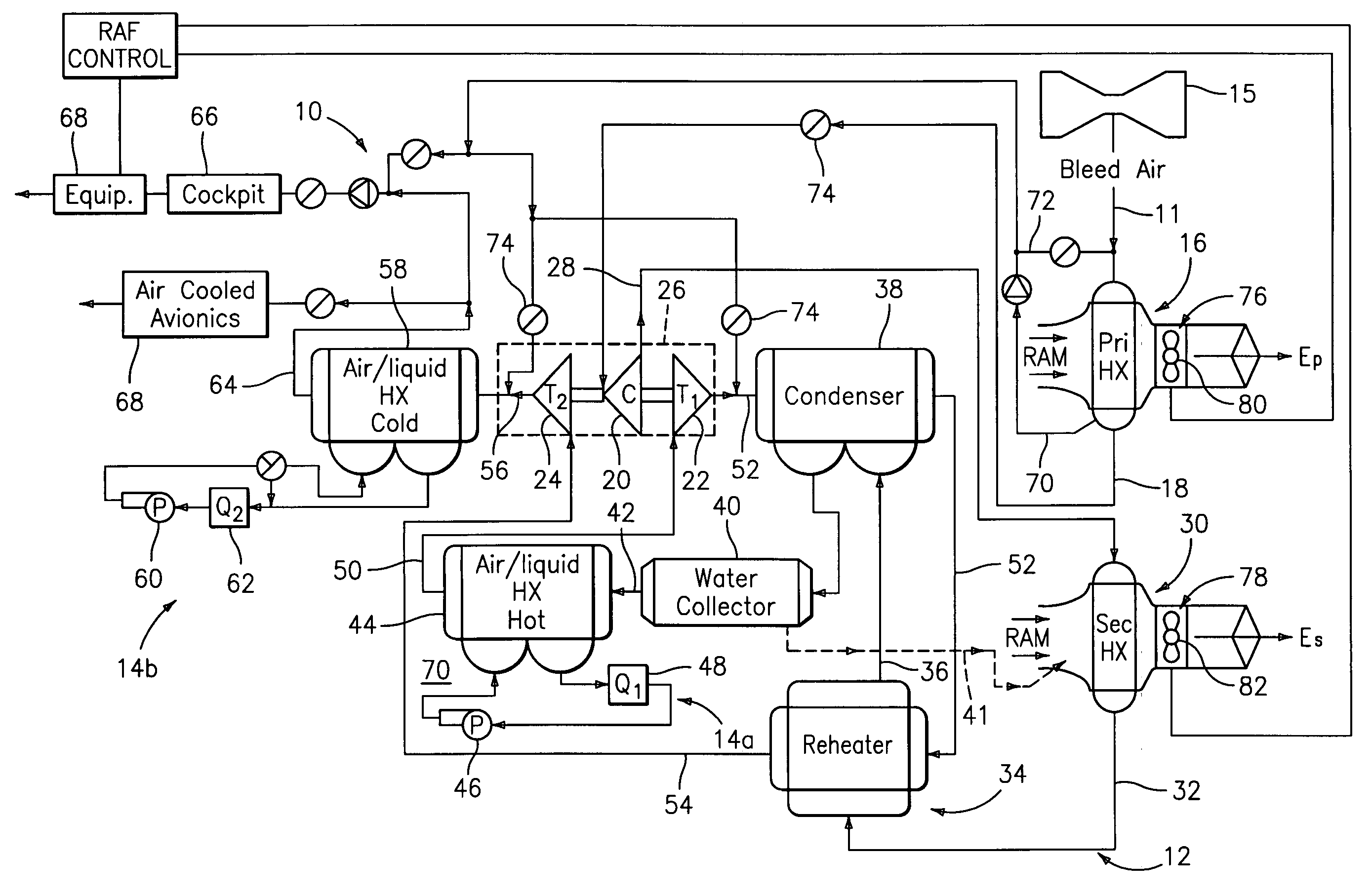
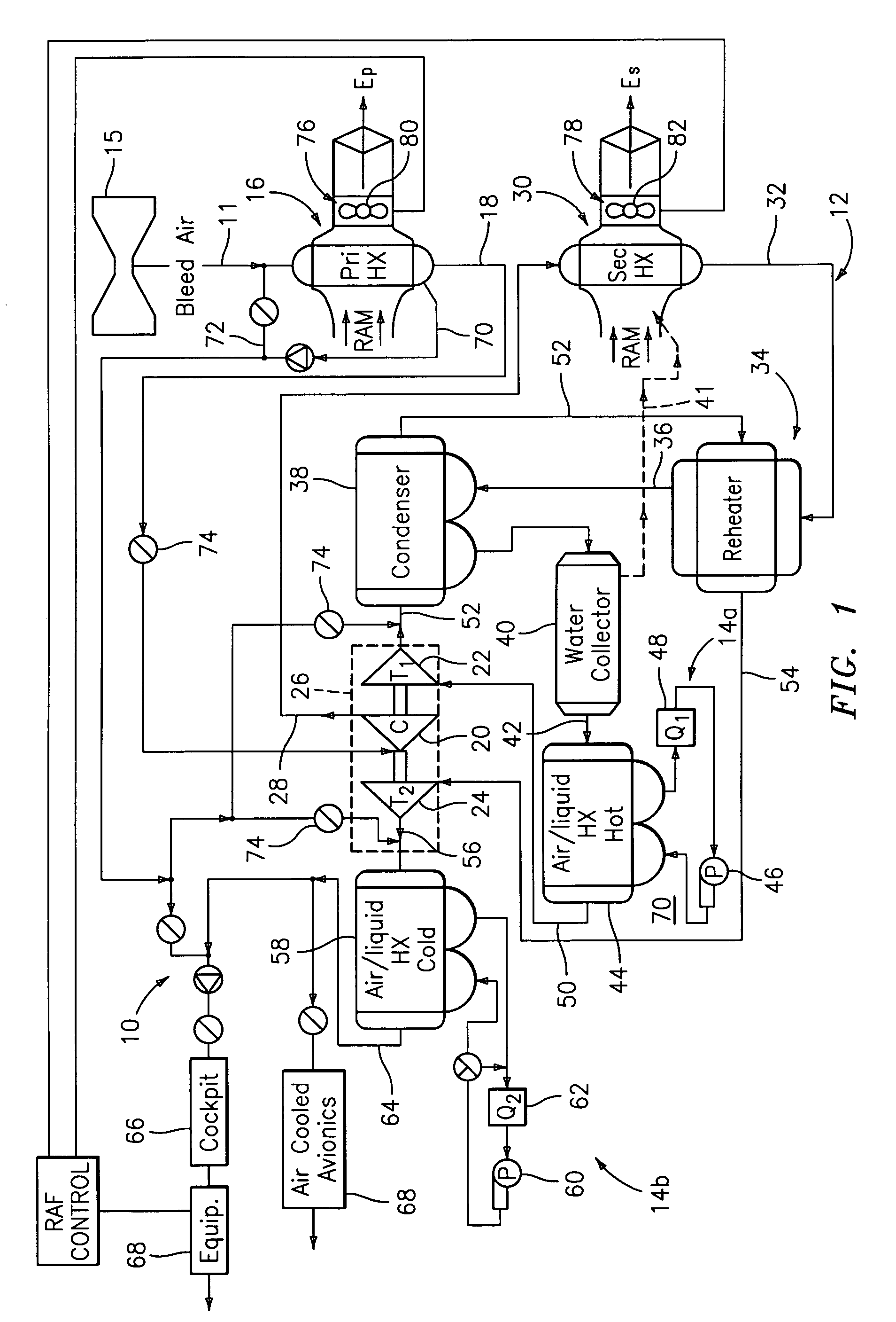
[0015]FIG. 1 illustrates a general schematic view of a liquid-to-air cycle system or environmental control system (ECS) 10. The ECS 10 includes an air cycle subsystem 12 that is in a heat exchange relationship with a liquid cycle subsystem 14a, 14b. It should be understood that although two separate liquid subsystems are disclosed in the illustrative embodiment, a single substantially continuous subsystem will also benefit from the present invention.

[0016]Bleed air 11 is preferably received from a gas turbine engine (illustrated schematically at 15). The bleed air 11 is sent through a primary heat exchanger 16 such that the bleed air 11 is in heat exchange relationship with RAM or ambient air. The primary heat exchanger 16 is preferably an air-to-air exchanger. After the bleed air 11 is cooled in the primary heat exchanger 16, the resulting cooler air is communicated through a passage 18 which communicates with a compressor 20 where the air is compressed to a high pressure. The comp...


PUM


Abstract

An ECS system includes an ACM mounted adjacent an air-liquid heat exchanger through a diffuser that contains a diffuser plate. The diffuser plate receives airflow from the ACM which strikes the diffuser plate and flows radially outward and around the diffuser plate and into the air-liquid heat exchanger to provide minimal pressure loss and proper flow distribution into the air-liquid heat exchanger with significantly less packaging space.

Description

BACKGROUND OF THE INVENTION[0001]This invention was made with government support under Contract No.: NAS2093146 awarded by NASA. The government therefore has certain rights in this invention.[0002]The present invention relates to environmental control systems (ECSs), and more particularly to an air cycle machine (ACM) heat exchanger interface.[0003]ECSs provide a supply of conditioned air to an enclosure, such as an aircraft cabin and cockpit. Conventional ECSs have utilized an air-to-air cycle cooling system which is in a heat exchange relationship with a liquid loop. The liquid loop typically cools other heat loads such as avionics packages. Interaction between the air and liquid subsystems may be relatively complex.[0004]The ACM communicates airflow from the turbine to the liquid-to-air heat exchanger through a diffuser. The diffuser requires gradual transitions from the circular turbine exit to the rectilinear heat exchanger inlet to minimize irrecoverable pressure losses and ac...

Claims


Application Information

Patent Timeline
Patent Type & Authority Applications(United States)
IPC IPC(8): F02C1/00
CPCB64D13/06B64D2013/0614B64D2013/0674Y02T50/56F28F9/0268Y02T50/44F28F9/0265Y02T50/40Y02T50/50
Inventor DECRISANTIS, ANGELO A.O'COIN, JAMES R.TADDEY, EDMUND P.
Owner HAMILTON SUNDSTRAND SPACE SYST INT
Why Eureka
Try Eureka