
Device for damping pressure pulsations for a compressor of a gaseous fluid

a technology of gaseous fluid and compressor, which is applied in the direction of pump components, positive displacement liquid engines, machines/engines, etc., can solve the problems of increasing pressure pulsation loss, generating noise, and insufficient propagation loss, so as to reduce compressor performance, reduce pressure loss, and specific damping

Active Publication Date: 2019-08-22
HANON SYST
View PDF9 Cites 1 Cited by
  • Summary
  • Abstract
  • Description
  • Claims
  • Application Information

AI Technical Summary

Benefits of technology

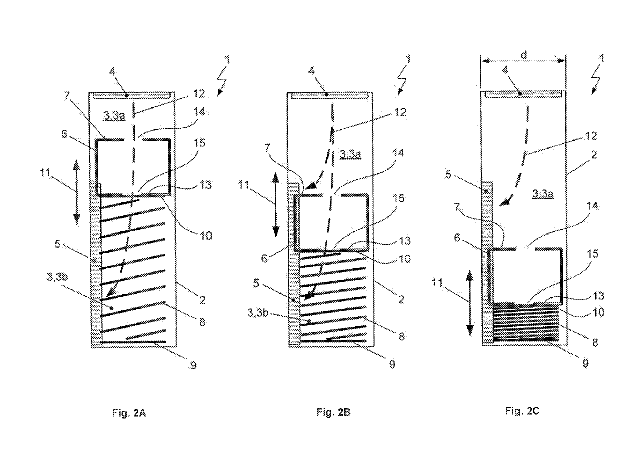
The invention is about a device that reduces pressure pulsations in a compressor for gas. It includes a housing, a piston, and a spring. The piston is held in the housing and can change its position to change the size of the chamber and the flow of gas coming out of the device. The piston has openings that act like a fluidic connection to change the pressure and damp the pulsations. The device can be used in refrigerant compressors and can help reduce pressure pulsations that can affect the performance of the compressor.

Problems solved by technology

The abrupt change of the flow cross section effects a rise of pressure pulsation loss which, in turn, reduces the pressure pulsation that is propagated through the refrigerant line of the refrigerant circulation into the interior of the vehicle and generates noise.
However, for some applications the propagation loss is not sufficient,
However, in implementing the device, inclusion of lubricant for the compressor circulating in the refrigerant circulation may occur.
Providing a damper with variable volume leads during the operation of the compressor to varying damping behaviour which deviates from the target frequency range and thus cannot effect a decrease of the pulsation.
Specifically, due to the distinct length of the flow path through the bypass, an enormous pressure drop occurs which effects a reduction of the compressor performance.

Method used


Image

  • Device for damping pressure pulsations for a compressor of a gaseous fluid
  • Device for damping pressure pulsations for a compressor of a gaseous fluid
  • Device for damping pressure pulsations for a compressor of a gaseous fluid

Examples


Embodiment Construction

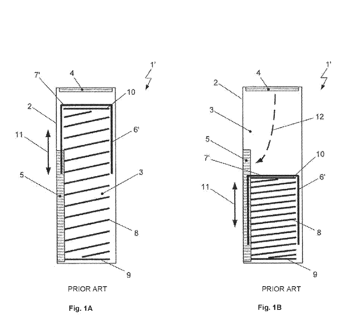
[0047]In FIGS. 1A and 1B is shown a device 1′ of prior art for damping pressure pulsations for a compressor within a chamber 3 encompassed by a housing 2 in sectional representation. In FIG. 1A the device 1′ is shown in a closed state, while the device 1′ according to FIG. 1B is shown in an opened state.

[0048]The housing 2 encompassing the chamber 3 comprises an inlet opening 4 as well as an outlet opening 5, each of which being implemented in the wall of the housing 2. The fluid to be compressed during its flow through the compressor flows through the inlet opening 4 into the chamber 3 and out of the chamber 3 through the outlet opening 5. The inlet opening 4 is developed as a connection to a low-pressure side of a refrigerant circulation, while the outlet opening 5 is connected with a suction region of the compressor. The inlet opening 4 is implemented in a wall closing off the chamber 3 at a first end face, while the outlet opening 5 is implemented on a wall closing off the chamb...


PUM


Abstract

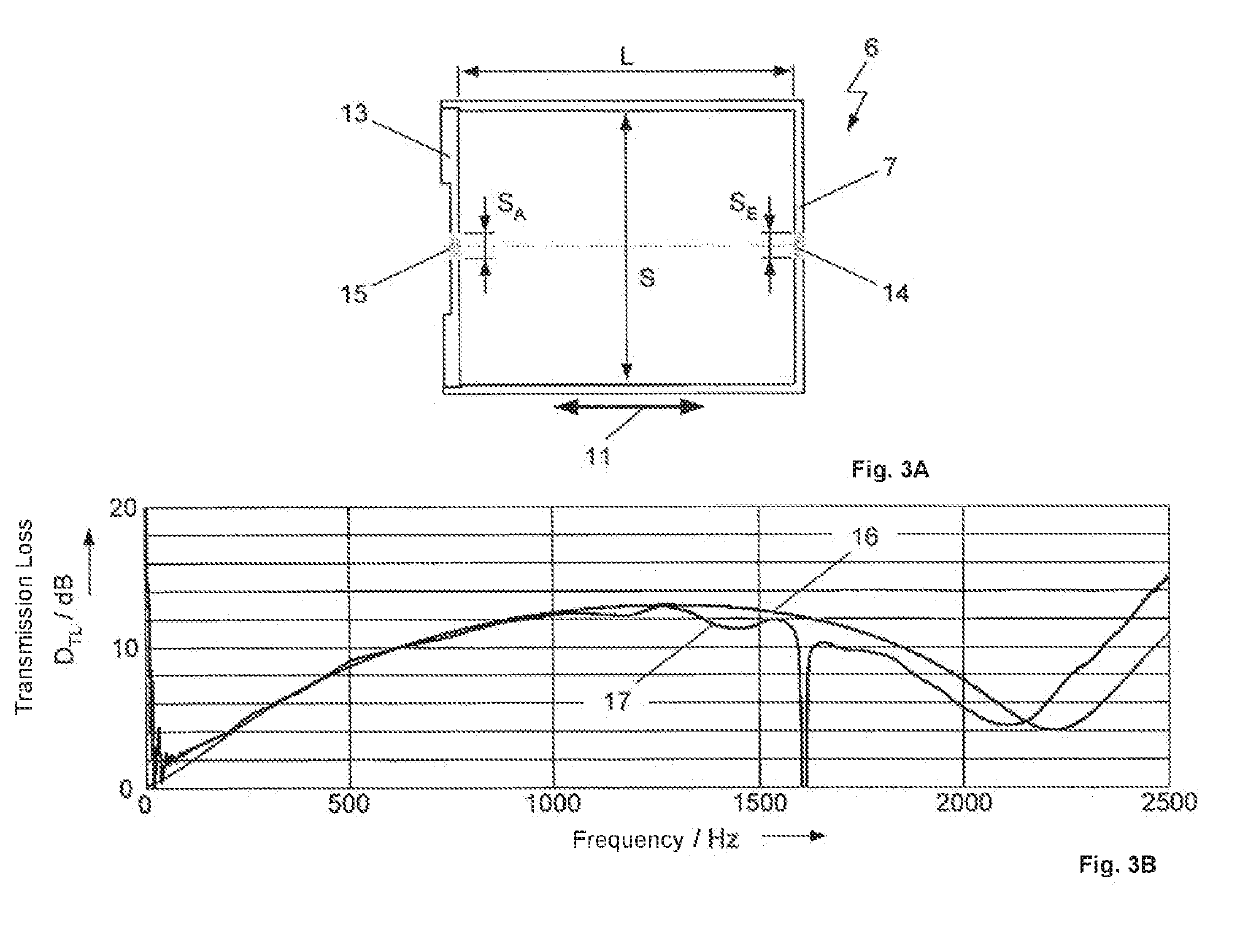
The invention relates to a device (1) for damping pressure pulsations for a compressor of a gaseous fluid, in particular of a refrigerant. The device comprises a housing (2), a piston element (6) as well as a spring element (8). The housing (2) is developed encompassing a chamber (3), with an inlet opening (4) and an outlet opening (5). The piston element (6), supported such that it is stayed across the spring element (8) on the housing (2), is disposed within the chamber (3) dividing the chamber (3) into a first chamber volume (3a) and a second chamber volume (3b), as well as being disposed movably in a direction of motion (11) between a first end position and a second end position. The motion of the piston element (6) effects a change of the chamber volumes (3a, 3b) and of a flow cross section of the outlet opening (5). The piston element (6) is developed as a hollow cylinder with two, at least partially closed, end faces (7, 13). The piston element (6) herein comprises at least one through-opening (14, 15) developed as a fluidic connection between a chamber volume (3a, 3b) and a volume encompassed by a wall of the piston element (6).

Description

[0001]This application claims priority from German Patent Application No, 10 2018 103 610.8 filed on Feb. 19, 2018, which is hereby incorporated herein by reference in its entirety.FIELD OF THE INVENTION[0002]The invention relates to a device for damping pressure pulsations for application in the compressor of a gaseous fluid, in particular of a refrigerant. The device comprises a housing, a piston element and a spring element. The housing is developed to encompass a chamber and comprises an inlet opening and an outlet opening. The piston element, supported such that it is stayed on the housing across the spring element, is disposed within the chamber dividing the chamber into a first chamber volume and a second chamber volume, and is as well disposed such that it is movable in a direction of motion between a first end position and a second end position. The motion of the piston element effects a change of the chamber volumes and of a flow cross section of the outlet opening.BACKGRO...

Claims


Application Information

Patent Timeline
Patent Type & Authority Applications(United States)
IPC IPC(8): F04B39/00
CPCF04B39/0055F04B39/121F04B39/122F04B39/0005F04B39/0066F04B39/12F04B39/123
Inventor KOCH, STEFFENBENJACK, PHILIPPGALLISCH, PHILIP
Owner HANON SYST
Learn More