
Filter device

a filter device and filter technology, applied in the direction of filtration separation, separation process, transportation and packaging, etc., can solve the problems of large mounting space, large filter size, and high pressure loss of filter, and achieve the effect of minimalism of spa

Inactive Publication Date: 2012-08-09
MANN HUMMEL GMBH
View PDF18 Cites 1 Cited by
  • Summary
  • Abstract
  • Description
  • Claims
  • Application Information

AI Technical Summary

Benefits of technology

[0005]It is therefore an object of the present invention to provide a filter device that has a filter action that is as high as possible and a pressure loss that is as minimal as possible and that requires only minimal space.
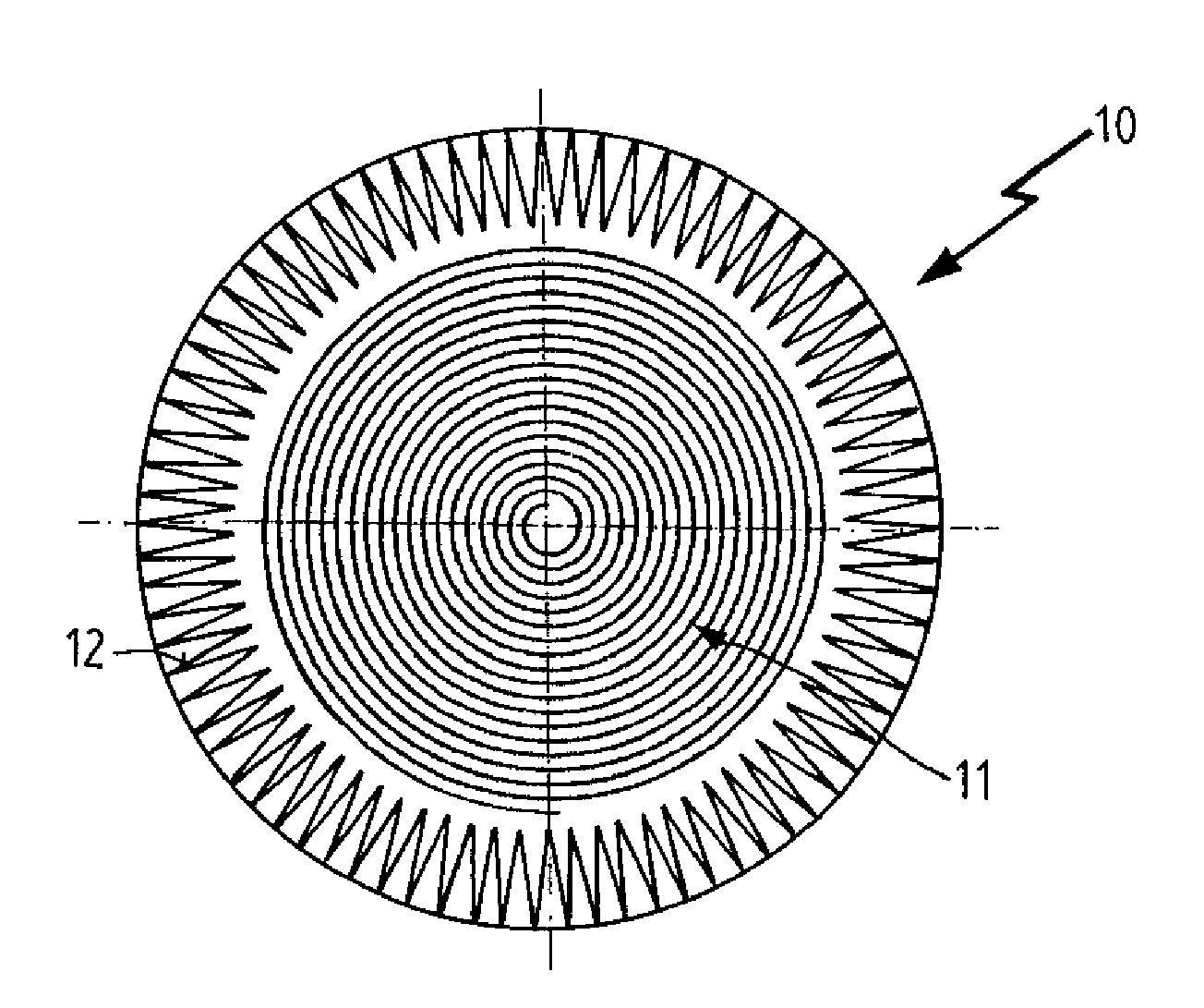
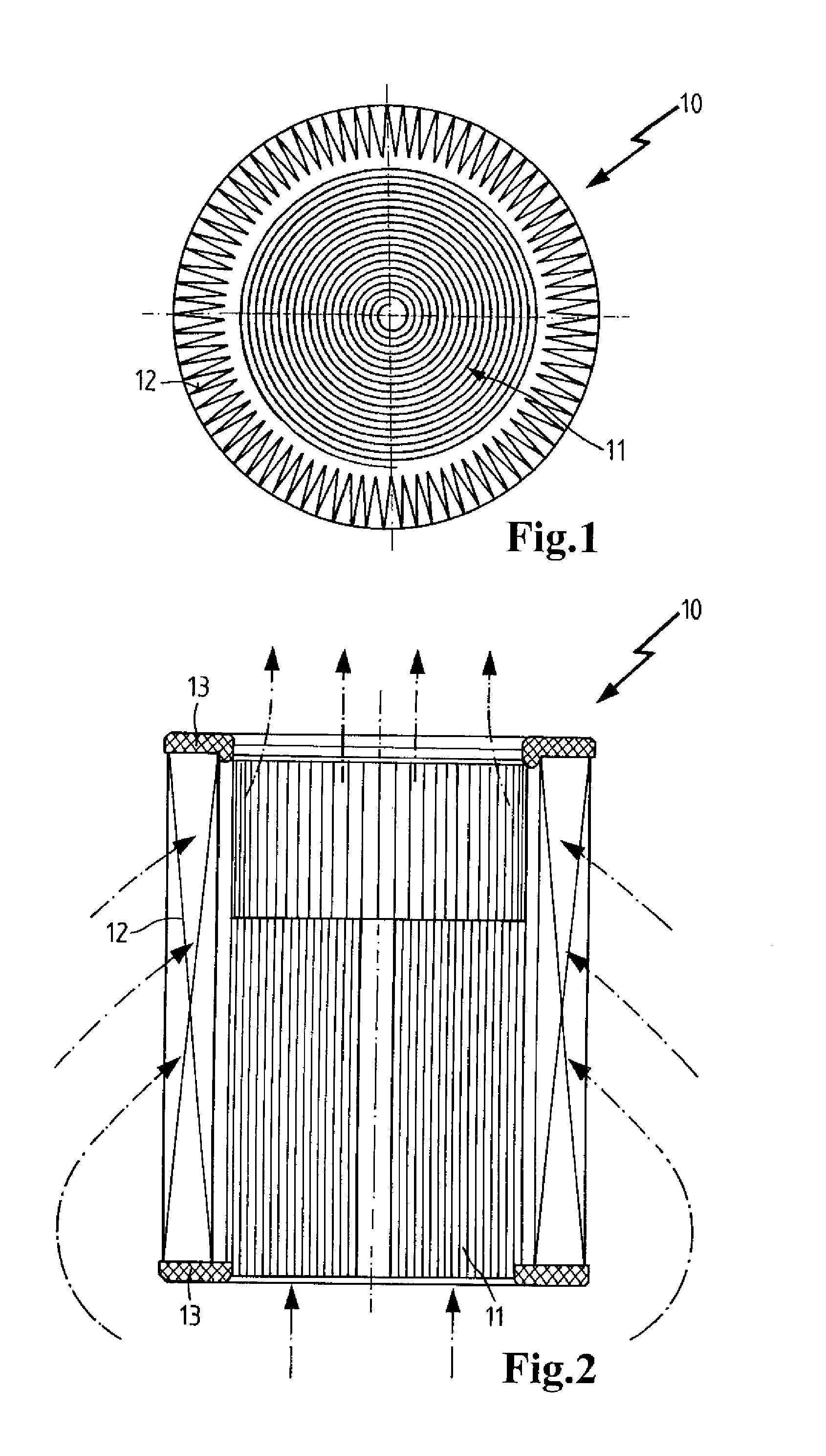
[0008]In particular, the filter device has a high filtering effect wherein the compact filter may have the greater filtering effect in comparison to the star filter, for example, with respect to the degree of separation and / or dust capacity. Even though the filtering effect of the compact filter is generally greater than that of the star filter, the star filter in comparison to the compact filter has usually the smaller pressure loss. Accordingly, the filter device, as a whole, has a comparatively high filtering effect while it exhibits simultaneously a minimal pressure loss and provides an optimal mounting space utilization.
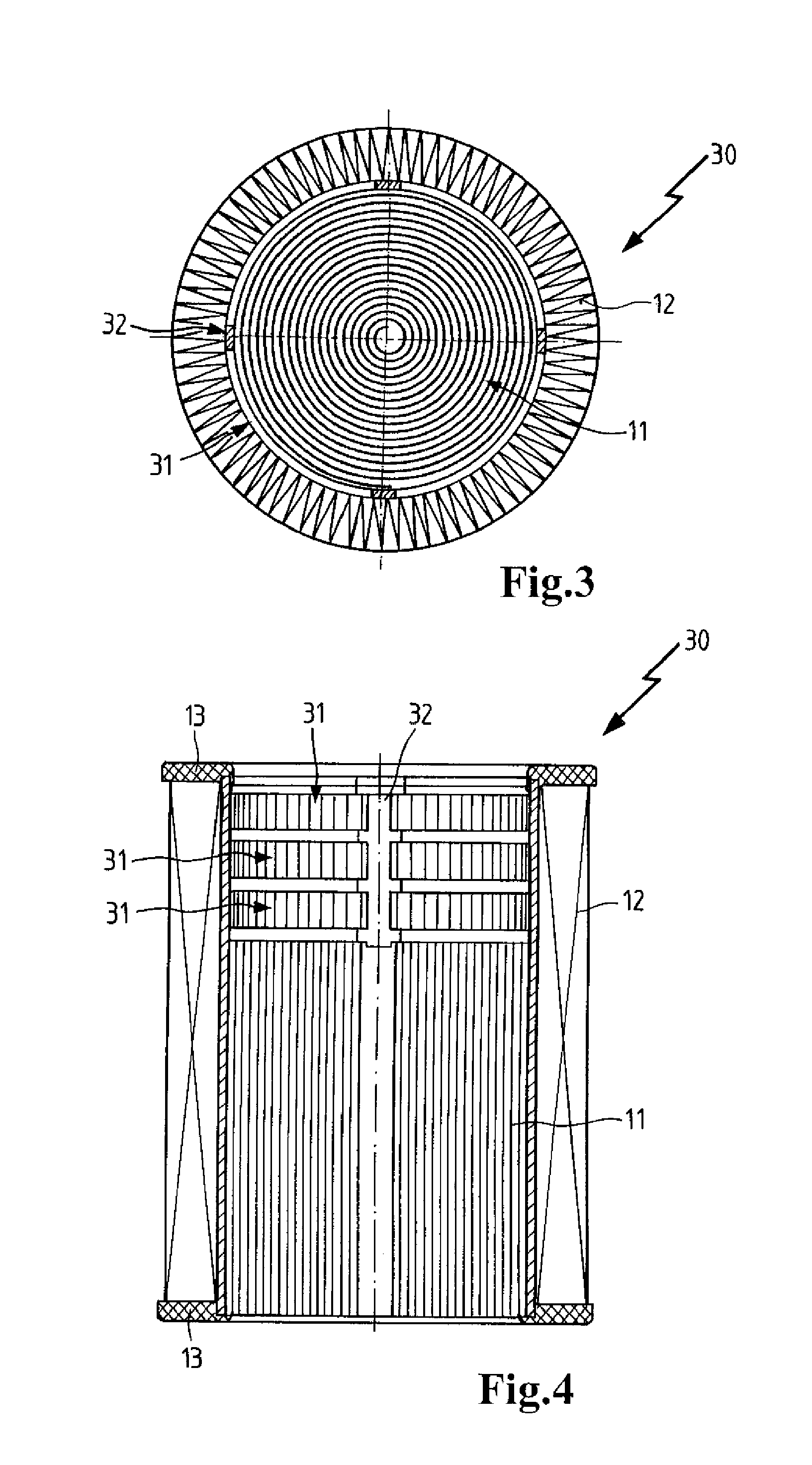
[0010]Between the compact filter and the star filter a tube (central tube) provided with penetrations can be arranged coaxially to the compact filter and to the star filter. The star filter can rest against the tube so that it supports the star filter and provides it with the desired shape stability. This can be particularly advantageous when the star filter has a greater length than the compact filter and thus projects past it with sections thereof.
[0012]The compact filter can be flowed through in axial direction by the air while the star filter can be flowed through in radial direction by the air. Accordingly, the filter device can be flowed through in axial and radial directions by the air. In this way, the flowed-through filter surface area can be maximized in the filter device.
[0015]Expediently, the compact filter and the star filter each can have different lengths. When the star filter is longer than the compact filter, this is beneficial with respect to reduction of pressure losses.
[0017]A secondary filter can be arranged in the flow direction downstream of the compact filter. The secondary filter can improve efficiently the filter action of the filter device. It can maintain also the filtering action when the compact filter and / or the star filter are to be exchanged. The secondary filter can be preferably a star filter.

Problems solved by technology

Such filters may exhibit a high pressure loss in particular when under great load.
Such filters, however, have a relatively large size and require a lot of mounting space.

Method used


Image

  • Filter device
  • Filter device
  • Filter device

Examples


Embodiment Construction

[0033]Before describing in detail embodiments that are in accordance with the present invention, it should be observed that the embodiments reside primarily in combinations of apparatus components related to a filter device. Accordingly, the apparatus components have been represented where appropriate by conventional symbols in the drawings, showing only those specific details that are pertinent to understanding the embodiments of the present invention so as not to obscure the disclosure with details that will be readily apparent to those of ordinary skill in the art having the benefit of the description herein.

[0034]In this document, relational terms such as first and second, top and bottom, and the like may be used solely to distinguish one entity or action from another entity or action without necessarily requiring or implying any actual such relationship or order between such entities or actions. The terms “comprises,”“comprising,” or any other variation thereof, are intended to...


PUM

PropertyMeasurementUnit
diameteraaaaaaaaaa
diameteraaaaaaaaaa
axial lengthaaaaaaaaaa

Abstract

A filter device has a compact filter made of a filter material that is wound spirally. A star filter that is made of a filter material that has folds arranged in a star shape surrounds the compact filter. The filter device has a cylindrical shape. A fluid to be filtered passes the compact filter in an axial direction and the star filter in a radial direction. The filter device is exchangeable and is mounted in a filter housing such that the compact filter and the star filter have a common raw side and a common clean side that are separated from each other.

Description

CROSS REFERENCE TO RELATED APPLICATIONS[0001]This application claims the benefit under 35 USC 119 of foreign application DE 102011009921.2 filed in Germany on Jan. 31, 2011, and which is hereby incorporated by reference in its entirety.TECHNICAL FIELD[0002]The invention relates to a filter device for filtering fluids, in particular for intake air, fuel, urea-water solutions or lubricant oil for internal combustion engines in motor vehicles.BACKGROUND OF THE INVENTION[0003]Filters that comprise spirally wound filter materials are known in the prior art. For the filtration of air, so-called compact filters are commonly used that are in particular formed of layered filter paper. A corrugated filter paper web is applied onto a flat filter paper web. The thus formed semi-finished product is wound to a filter body or stacked so that a plurality of gas passages that extend parallel to each other are formed. These gas passages are alternatingly closed off by plugs. Incoming air passes axial...

Claims


Application Information

Patent Timeline
Patent Type & Authority Applications(United States)
IPC IPC(8): B01D29/54
CPCB01D46/0024B01D46/528B01D46/522B01D46/64
Inventor MAARADJI, YASSINEHAHN, JENSZINK, JAN KARLSTINZENDORFER, JOACHIMBECKER, STEFANMUNKEL, KARLHEINZWOLF, MICHAELBLOSSEY, WERNERRIEGER, MARIOPOH, RALFROHRMEIER, JOSEFSIEBER, THOMASPELZ, ANDREASSANDERS, ROLFWINTER, MANFRED
Owner MANN HUMMEL GMBH
Learn More