Optimizing the efficiency and energy usage of a geothermal multiple heat pump system

a geothermal multiple heat pump and efficiency optimization technology, applied in heat pumps, lighting and heating apparatus, heating types, etc., can solve the problems of inefficient operation of geothermal loop, low flow rate through plastic piping usually used, and multiple heat pump systems providing no means of reducing electrical demand, so as to optimize the efficiency of the overall system and optimize the coefficient of performance

Active Publication Date: 2015-12-01
SIEGENTHALER JOHN
View PDF21 Cites 1 Cited by
  • Summary
  • Abstract
  • Description
  • Claims
  • Application Information

AI Technical Summary

Benefits of technology

[0003]The present invention broadly provides an operating geothermal heat pump system that allows the operator to optimize the efficiency of the overall system by allowing variation of the earth loop flow rate depending upon the load requirements of, e.g., a single variable heat pump system or a multiple heat pump load loop, while optimizing circulator speed control in a multiple geothermal heat pump system. The system controlled in accordance with this invention avoids any problems that may be caused by slowing the circulators so that laminar flow results in the geothermal, or earth loop. The present invention comprises a system, and a method of operating the system, that allows for the optimization of the Coefficient of Performance of the system by permitting continuous variation of the earth loop flow rate as needed to balance the load requirement from the heat pump loop side of the system. Furthermore, where the flow rates for each of the two loops can be varied independently of each other as conditions change, i.e., where there are separate circulators for each of the earth loop and the heat pump loop. This invention provides a system that avoids any problem that may arise from low instantaneous heat transfer rate during laminar flow in the earth loop.
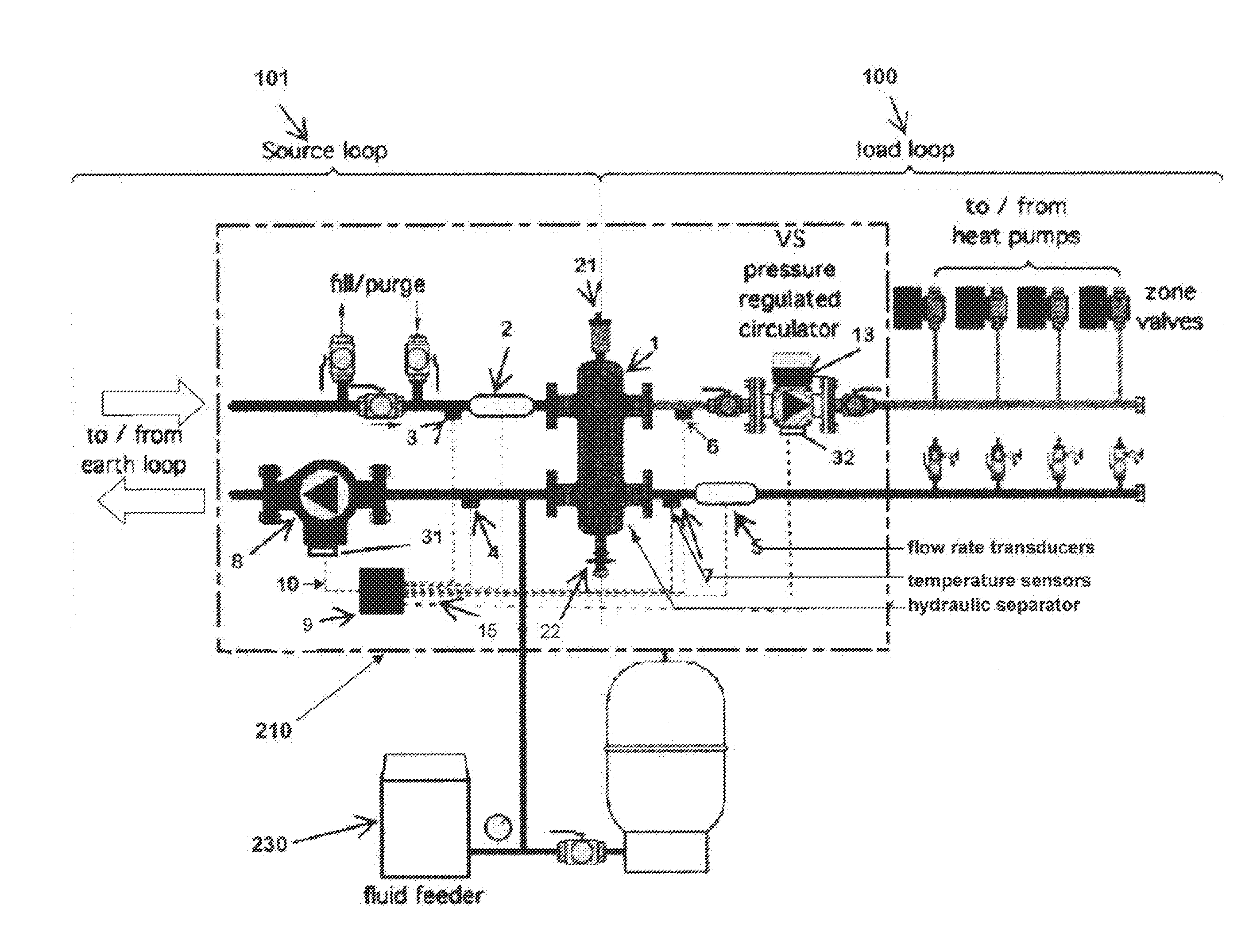
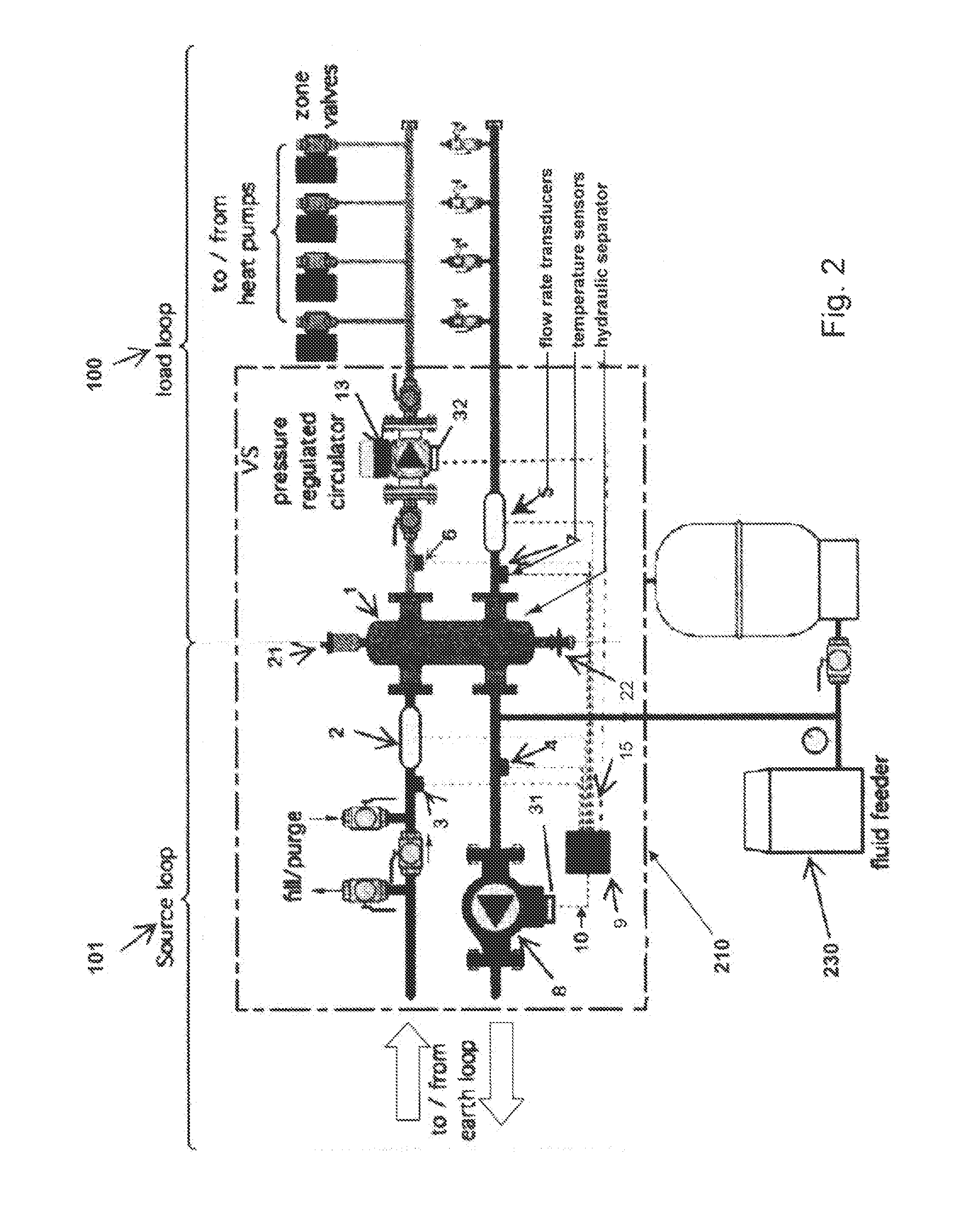
[0005]The hydraulic separator interconnects fluid flow through the two loops, but allows for separate independent, unlimited fluid flow adjustments of the ground loop flow and the heat pump, or load, loop flow, in order to accommodate large changes in the heat exchange rate required for the load loop while maintaining complete and effective heat exchange between the two loops; for example, where multiple heat pumps are provided in a single building or group of buildings, and all or only one of the heat pumps may be operating at any given time; depending upon the needs of the building's occupants, the heat requirement of the load loop may be 20% or less than that required at full operation. The hydraulic separator provides a volume for mixing and heat exchange of the liquid flowing through the two loops with minimal pressure loss, while permitting independently setting the flow rate through each loop. The hydraulic separator also provides the added benefit of optimally providing for the removal of air bubbles and any suspended particulate material, and thus prevent buildup of these impurities, which could compromise the efficient, long term operation of the heat pump system.
[0007]Many suppliers manufacture specially arranged hydraulic separators, which also may contain coalescing medium to assist in the removal of air microbubbles and suspended solid particles. Alternatively, a similar effect is obtainable by the use of a wide diameter vertical header, having centrally located along the length of the header a pair of closely spaced T's.
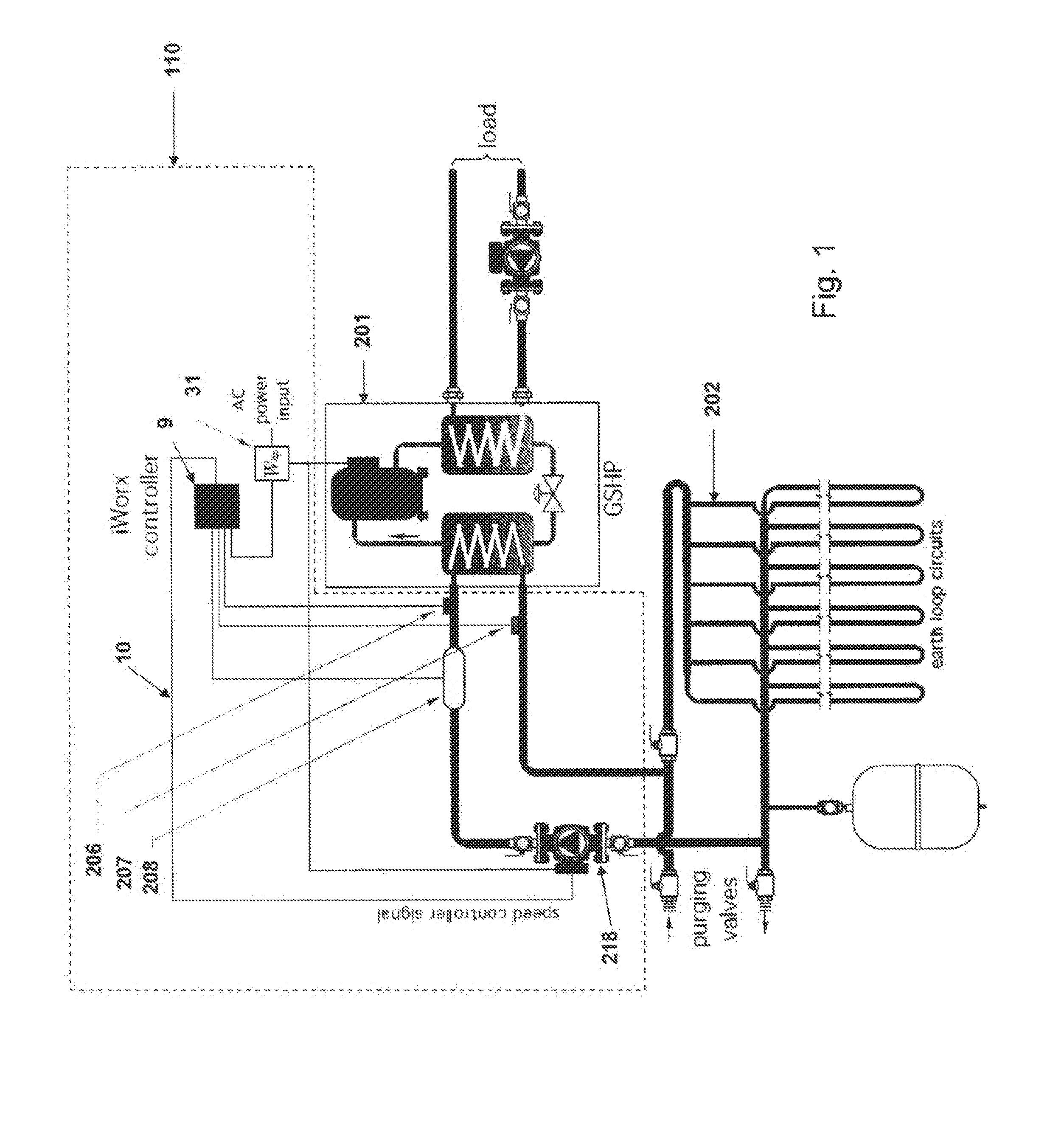
[0009]This compact package can efficiently and effectively monitor and control the two loops and optimize the efficiency of the system in accordance with the method of the present invention. The data controller continuously receives temperature and flow rate data from each of the temperature sensors and flow rate transducers, and power usage from each watt transducer, to compute the instantaneous heat exchange rate for each loop, and the power usage of the system, and thus the Coefficient of Performance (“COP”) of the system. By varying the speed of the ground loop circulator in accordance with the heat flow requirements of the load loop fluid, it can maintain the required temperatures in the load loop system while optimizing the energy use efficiency (COP) of the overall system.
[0011]In accordance with the method of this invention, the digital data controller is programmed to use the data provided by the several sensors and transducers to operate the geothermal heat pump system in accordance with the algorithm of this invention, so as to optimize the Coefficient of Performance (“COP”) of the overall system, and to optimize the respective flow rates of each of the ground loop and load loop to achieve the most effective heat exchange rates and operating conditions. By allowing for the operation of the ground loop at laminar flow conditions, even for short periods of time, the total energy usage by the circulators, and therefore the overall efficiency of the system is improved.
[0012]The method of this invention is represented by algorithms programmed into the data controller. The method of this invention provides for balancing the instantaneous heat exchange rate between the two loops by varying the speed of the ground loop circulator in response to changes in the required instantaneous heat exchange rate for the load loop so as to control the fluid flow rates of the ground loop in order to optimize the overall efficiency; by modifying the energy usages of the two loops so as to reduce the total energy usage, overall efficiency is improved.

Problems solved by technology

At times of low heat pump operation, the operation of the geothermal loop was inefficient in the sense that unnecessary energy was being expended in maintaining constant flow through the geothermal loop.
The prior art believed either that it was necessary to maintain a high flow through the ground loop in order to maintain turbulent flow; although some workers believed that the primary limiting parameter for geothermal heat flow was the low heat transfer rate through the plastic piping usually used.
Therefore, existing geothermal multiple heat pump systems provide no means of reducing the electrical demand of the earth loop circulator when a multiple heat pump array is operating at less than full capacity.

Method used


Image

  • Optimizing the efficiency and energy usage of a geothermal multiple heat pump system
  • Optimizing the efficiency and energy usage of a geothermal multiple heat pump system
  • Optimizing the efficiency and energy usage of a geothermal multiple heat pump system

Examples


Embodiment Construction

[0019]The operation of systems of this invention, in accordance with the general depictions of FIGS. 1 and 2, is preferably carried out using a digital controller 9, programmed in accordance with the algorithms represented by the flow charts of FIGS. 6 and 7, respectively. The program comprises a series of mathematical equations that are used to calculate the various parameters of the system, based upon data received by the controller 9 from the several sensors, and pre-entered information, such as the known properties of the circulating fluid, e.g., its specific heat and density. The data received provide the bases for controlling the earth loop circulator 8, by optimizing the flow through the earth loop 101, which tends to enhance the coefficient of performance (COP) of the overall system, and to maintain the instantaneous rate of heat transfer (Qearthloop) on the earth, or Source, loop side 101 of the hydraulic separator 1, at a value not less than the heat transfer (Qoutput) for...


PUM


Abstract

A system and a method for operating the system is provided to optimize heat exchange between a geothermal loop and a heat pump load loop for heating and cooling a structure. In the method, the flow rate through the earth loop is adjusted based on current thermal demand of a heat pump array, so as to reduce the electrical demand of the earth loop circulator when thermal demand from the heat pump loop is low. The method adjusts the speed of the earthloop circulator as required for the operating conditions of the heat pumps and earth loop, thereby permitting efficient laminar flow whenever possible, as long as thermal demand is met.The system of this invention provides a compact module containing a suitable digital data receiver and controller programmed to receive temperature and flow data and to calculate the needed flow in each loop to meet the thermal demand of the heat pump or pumps, and to signal the earthloop pump, and optionally a load loop pump, to operate at the necessary flow speed. Specifically, if flow in the earth loop transitions from turbulent to laminar, this method insures that the current thermal demand of the heat pumps is met, and if not, increasing the earth loop circulator speed to deliver the current thermal demand of the heat pumps.

Description

[0001]This application is a division of U.S. patent Ser. No. 12 / 947,342, filed on Nov. 16, 2010, which applicatilon claims the benefit of priority pursuant to 35 U.S.C. 119(c) from U.S. provisional patent application having Application No. 61 / 262,030, filed on Nov. 17, 2009.BACKGROUND OF THE INVENTION[0002]It is well-known to provide geothermal sources for systems of heat pumps for the heating or cooling of residential, commercial or industrial buildings. It has generally been assumed that the ground loop circulation remains constant even when used with multiple heat pump systems, where there can be widely varying energy requirements depending upon the number of heat pumps operating at any given time. For example, many office buildings are substantially empty overnight, so that the heat pumps maintained in operation during that period may vary by as much as a factor of 5, or more, as compared to the heat pumps operated during a business day. At times of low heat pump operation, the ...

Claims


Application Information

Patent Timeline
Patent Type & Authority Patents(United States)
IPC IPC(8): F25B7/00F28F27/00F24J3/08
CPCF28F27/00F24J3/08F24D11/004F24T10/00F24T10/10F24T2010/56F25B30/06F25B2500/19F25B2600/13F25B2700/13Y02B30/70Y02E10/10
Inventor SIEGENTHALER, JOHN
Owner SIEGENTHALER JOHN
Why Eureka
Try Eureka