Condenser Ice Removal for Environmental Control System

a technology of environmental control system and condenser, which is applied in the direction of ventilation system, lighting and heating apparatus, heating types, etc., can solve the problems of reducing the air flow of aircraft, raising challenges, and causing ice to become a particular problem

Active Publication Date: 2014-06-19
HAMILTON SUNDSTRAND CORP
View PDF13 Cites 13 Cited by
  • Summary
  • Abstract
  • Description
  • Claims
  • Application Information

AI Technical Summary

Benefits of technology

The patent describes an environmental control system for an aircraft that uses a heat exchanger to cool down hot air. A fan pulls in cooling air, and the hot air is compressed and then driven through a turbine. The system also includes an icing control system that can adjust the flow of hot air to prevent ice formation on the surfaces of the system. The technical effect of this system is to improve the efficiency and reliability of the environmental control system, which is important for safe and successful operation of the aircraft.

Problems solved by technology

The technical problem addressed in this patent is how to prevent ice formation on the condenser of an environmental control system of an aircraft, especially when the air is too cold and there is too much ram air flow. The current method of using an on/off valve to add hot air to the inlet of the condenser and a second stage turbine is not sufficient to maintain the temperature above freezing, which can lead to undesirable consequences.

Method used


Image

  • Condenser Ice Removal for Environmental Control System
  • Condenser Ice Removal for Environmental Control System

Examples


Embodiment Construction

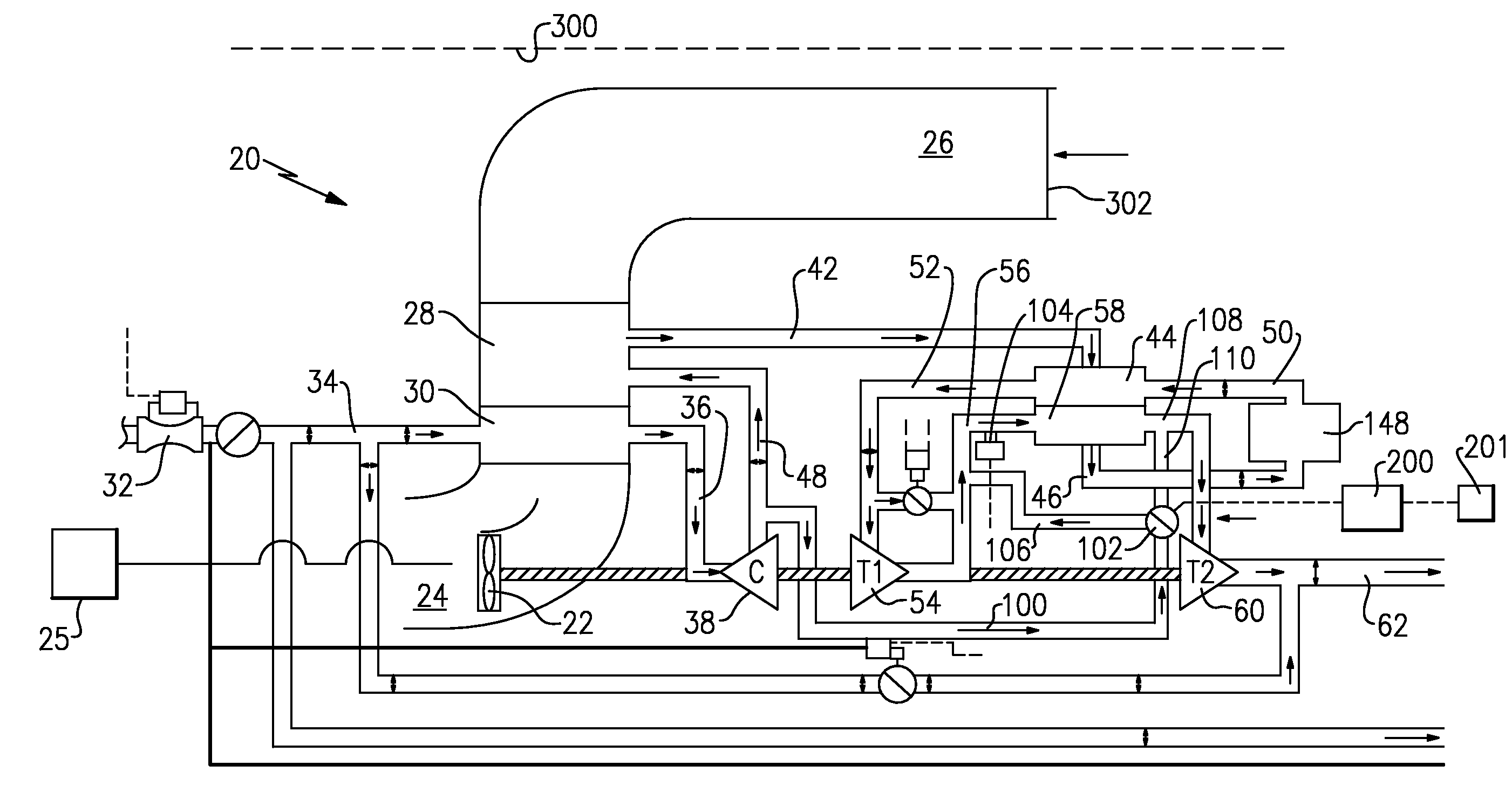
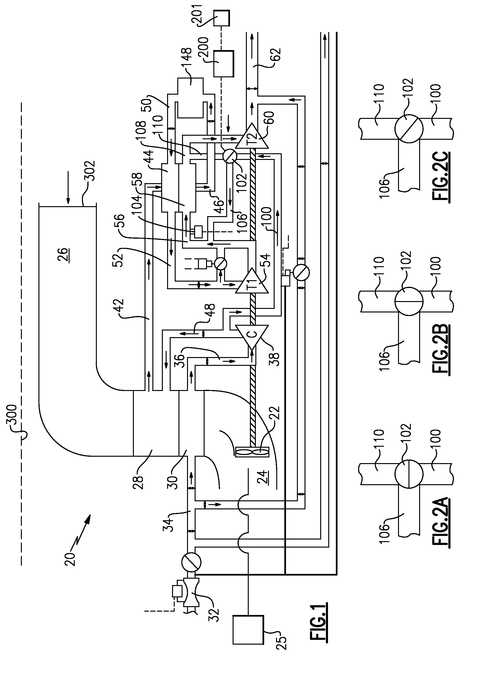
[0012]An environmental control system 20 is illustrated in FIG. 1. A bleed air source enters the environmental control system 20 by an inlet duct 32 and continues to flow to ducting 34. Since the bleed air is hot, the inlet air is cooled at a primary heat exchanger 30, and a secondary heat exchanger 28. The cooling source is the ambient air that is pulled by a fan 22 from a ram inlet duct 26 to an outlet 24. The ram inlet duct 26 communicates with an opening 302 which is on an outer surface of an aircraft 300, shown schematically. Notably, the air in the ram inlet duct 26 does not mix with the interior of the heat exchangers 28 or 30, but rather passes across them such that the bleed air 32 is cooled.

[0013]After the bleed air passes the primary heat exchanger 30 the air passes into a flow line 36, and to a compressor 38. Downstream of a compressor 38 the air passes into a line 48 leading into a secondary heat exchanger 28. Secondary heat exchanger 28 further cools the air. The air d...


PUM


Abstract

Environmental control system bleed air is cooled by a heat exchanger. A fan pulls ambient air from a ram inlet duct across the at least heat exchanger and to an outlet. An air cycle machine drives the fan. The bleed air passes downstream of the at least heat exchanger to a compressor, and then drives a first stage turbine. The first stage turbine has an outlet communicating with a condenser, and then a second stage turbine. An icing control system taps hot air downstream of the compressor. An add heat valve is selectively moveable between a first position blocking flow from the tap passage. A second position where it passes air from the tap passage to the condenser inlet, and to a point downstream of the condenser and to the second stage turbine. In a third position, the valve only communicates air from the tap passage into the condenser.

Description


Claims


Application Information

Patent Timeline
Owner HAMILTON SUNDSTRAND CORP
Why Eureka
Try Eureka