Aircraft environmental conditioning system and method

a technology for environmental conditioning and air conditioners, applied in the direction of domestic cooling devices, energy-efficient board measures, lighting and heating devices, etc., can solve the problems of reducing cooling performance, fan blade breakage, and particulate debris accumulation on and around the heat absorption sid

Inactive Publication Date: 2015-11-05
HAMILTON SUNDSTRAND CORP
View PDF5 Cites 13 Cited by
  • Summary
  • Abstract
  • Description
  • Claims
  • Application Information

AI Technical Summary

Problems solved by technology

Some of these conditions can involve exposure to airborne particulates, which can result in the accumulation of particulate debris on and around the heat absorption side of heat exchangers that use external air to absorb heat from the bleed air.
Continued accumulation of such debris can ultimately lead to partial to complete or near-complete airflow blockage on the heat absorption side of the heat exchanger, which can result in reduced cooling performance, heat exchanger fan problems such as fan surge, broken fan bla...

Method used


Image

  • Aircraft environmental conditioning system and method
  • Aircraft environmental conditioning system and method

Examples


Embodiment Construction

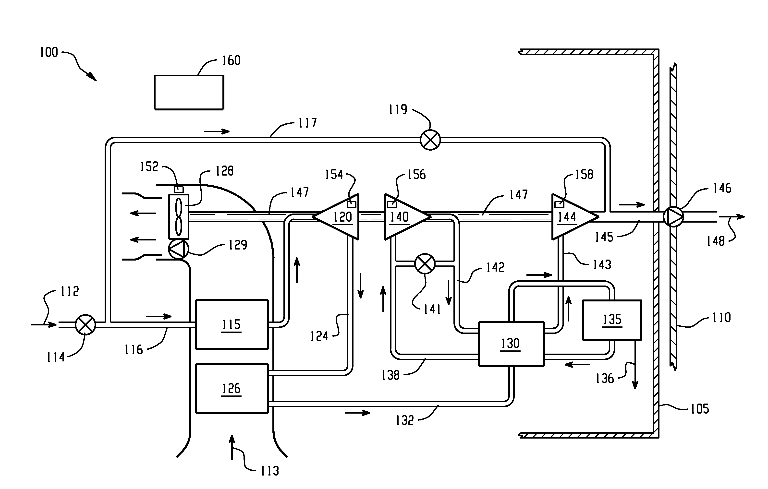
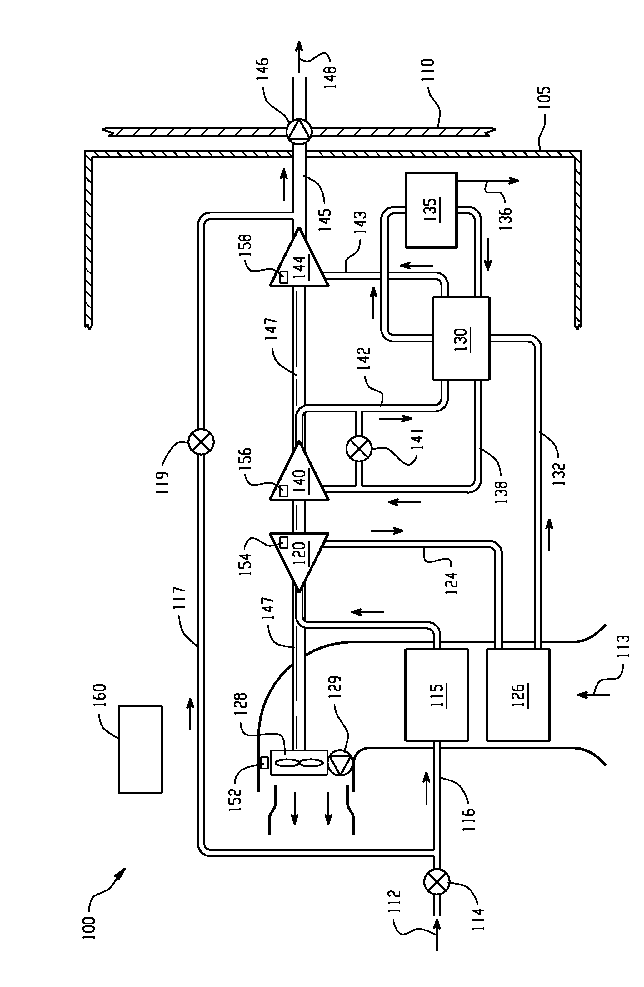
[0008]With reference to the FIGURE, the FIGURE schematically depicts an exemplary environmental air conditioning system 100 for an aircraft. The environmental air conditioning system 100 is inside housing 105 (only a portion of housing 105 is shown) disposed in an unpressurized area of an aircraft, separated from a pressurized area by bulkhead 110. As shown in the FIGURE, compressed air 112 from a compressed air source (not shown) such as a turbine engine bleed, an APU bleed, or an electrically-powered compressor is delivered through control valve 114 and conduit 116 to heat exchanger 115 (also referred to in the art as a primary heat exchanger) where it rejects heat to ambient air flowing through or across a heat absorption side of heat exchanger 115. Cooled compressed air is discharged from heat exchanger 115 to compressor 120. A portion of the air going to heat exchanger 115 can be controllably diverted through conduit 117 and control / expansion valve 119 to mix with the outlet of...


PUM


Abstract

An aircraft environmental conditioning system is disclosed having an air cycle machine for conditioning an airflow comprising hot compressed air by reducing its temperature and pressure. The air cycle machine is disposed in a housing in an unpressurized area of the aircraft, and produces conditioned pressurized air for delivery to a pressurized area of the aircraft. The system also includes a vibration sensor disposed within the housing, and a controller in communication with the vibration sensor that is configured to respond to vibration detected by the vibration sensor.

Description

CROSS-REFERENCE TO RELATED APPLICATIONS[0001]This patent application claims priority to U.S. Provisional Patent Application Ser. No. 61 / 988,031, filed May 2, 2014, which is incorporated herein by reference in its entirety.BACKGROUND OF THE INVENTION[0002]This invention relates to environmental air conditioning systems (ECS), and more specifically to air cycle environmental air conditioning systems such as used on aircraft.[0003]Aircraft that fly at altitudes above that at which ambient air is suitable for crew, passengers, cargo, or equipment are often equipped with air cycle environmental air conditioning systems to provide pressurized conditioned air. These air conditioning systems typically utilize a pressurized air bleed from a turbine fan engine or an auxiliary power unit (APU), or in some cases from an electrically-powered compressor as a source of compressed air that flows along an airflow path through the air cycle environmental air conditioning system to produce conditioned...

Claims


Application Information

Patent Timeline
IPC IPC(8): B64D13/06F02C6/08
CPCB64D13/06F02C6/08B64D2013/064B64D2013/0648B64D2013/0618Y02T50/50B64D2013/0603
Inventor LUKENS, WILLIAM H.ROG, LYNN M.D'ORLANDO, PAUL M.DEVITA, FRANCESCO A.GATZURAS, JOHN T.HOYT, WILLIAM D.
Owner HAMILTON SUNDSTRAND CORP
Why Eureka
Try Eureka