Air cycle machine strut plate assembly

a technology of air cycle machine and strut plate, which is applied in the direction of liquid fuel engine, forging/pressing/hammering apparatus, lighting and heating apparatus, etc., can solve the problems of fan rotor closer to surge limit, heat exchanger can become partially blocked, and performance reduction

Active Publication Date: 2016-04-07
HAMILTON SUNDSTRAND CORP
View PDF1 Cites 14 Cited by
  • Summary
  • Abstract
  • Description
  • Claims
  • Application Information

AI Technical Summary

Problems solved by technology

While in service, the heat exchanger can become partially clogged due to dust or other contaminants that reduce available flow volume to the fan rotor, which pushes the fan rotor closer to its surge limit.
Designs

Method used


Image

  • Air cycle machine strut plate assembly
  • Air cycle machine strut plate assembly
  • Air cycle machine strut plate assembly

Examples


Embodiment Construction

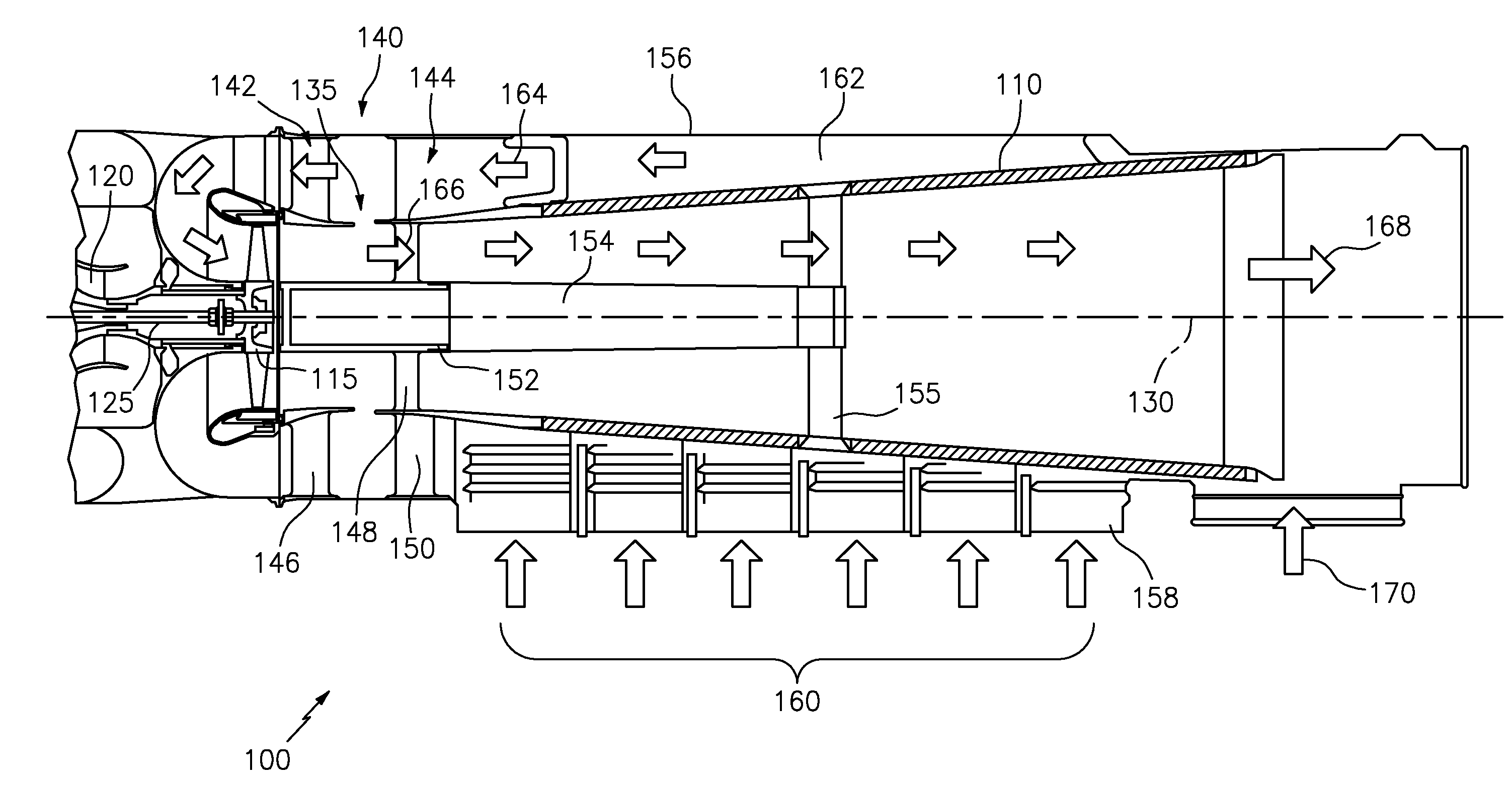
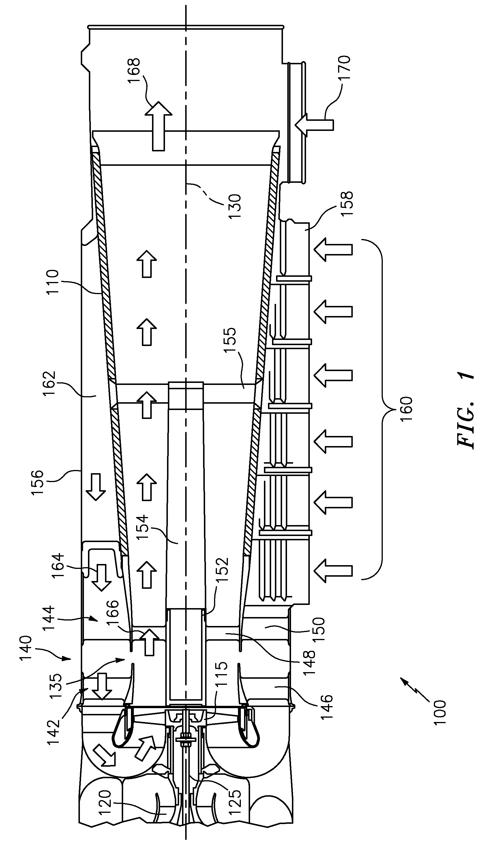
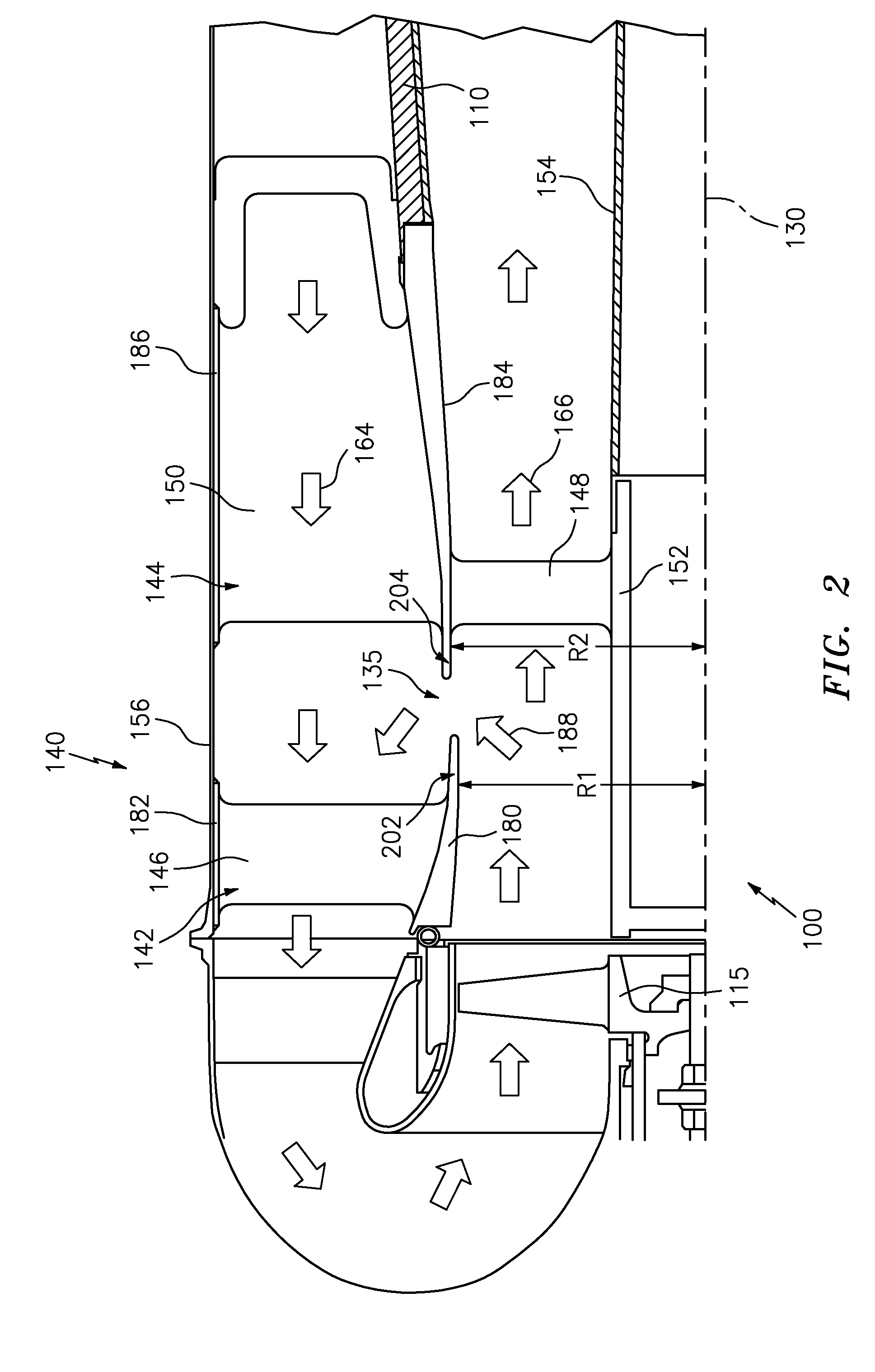
[0013]Embodiments of an environmental control system having an air cycle machine include a strut plate assembly with an ejector formed between a pair of strut plates as further described herein. The strut plate assembly can be axially positioned between a fan rotor and a diffuser cone of the air cycle machine. A first strut plate that is between the fan rotor and the ejector has outer struts but no inner struts, thereby reducing ejector blockage and swirl angle effects that can occur if inner struts are positioned between fan rotor and the ejector. A second strut plate includes both inner and outer struts and is axially positioned between the fan rotor and the diffuser assembly. The inner struts of the second strut plate are downstream of the ejector and can be angled and shaped to align with a design point condition of the fan rotor.

[0014]Referring to the drawings, FIG. 1 illustrates an example air cycle machine (ACM) 100 according to an embodiment of the invention. Particularly, t...


PUM

PropertyMeasurementUnit
Radiusaaaaaaaaaa
Velocityaaaaaaaaaa

Abstract

According to one aspect, an air cycle machine includes a fan rotor, a diffuser cone axially aligned with the fan rotor, and a strut plate assembly. The strut plate assembly includes a first strut plate and a second strut plate with an ejector formed between the first strut plate and the second strut plate. The first strut plate is axially positioned between the fan rotor and the ejector, and the second strut plate is axially positioned between the fan rotor and the diffuser cone. The first strut plate includes a plurality of outer struts and is absent inner struts between the fan rotor and the ejector. The second strut plate includes a plurality of inner struts and outer struts, where the inner struts are axially positioned between the ejector and the diffuser cone.

Description

BACKGROUND OF THE INVENTION[0001]The subject matter disclosed herein relates to an air cycle machine and, more particularly, to a strut plate assembly for an air cycle machine.[0002]Conventional aircraft environmental control systems (ECSs) incorporate an air cycle machine, also referred to as an air cycle cooling machine, for use in cooling and dehumidifying air for an aircraft cabin. Such air cycle machines may include two or more wheels disposed at axially spaced intervals along a common shaft. The wheels are part of, for example, a compressor rotor, a turbine rotor, a fan rotor or an additional turbine rotor or an additional compressor rotor. In some cases the turbine or turbines drive both the compressor and the fan.[0003]On aircraft powered by turbine engines, the air to be conditioned in the air cycle machine is typically compressed air bled from one or more of compressor stages of the turbine engine. In conventional systems, this bleed air passes through the air cycle machin...

Claims


Application Information

Patent Timeline
IPC IPC(8): F04D29/54B23P15/04F04D19/00
CPCF04D29/545B23P15/04F04D29/542F04D19/002B64D13/06F04D19/00F04D27/0215F04F5/16F25B9/004
Inventor BEERS, CRAIG M.HIPSKY, HAROLD W.
Owner HAMILTON SUNDSTRAND CORP
Why Eureka
Try Eureka