Vacuum cleaner with filter cleaning means

a vacuum cleaner and filter technology, applied in the direction of cleaning filter means, auxillary pretreatment, separation processes, etc., can solve the problems of clogging the filter, reducing the vacuum cleaning efficiency, so as to reduce the air flow through the vacuum cleaner and achieve efficient sealing

Active Publication Date: 2013-04-23
AB ELECTROLUX
View PDF184 Cites 67 Cited by
  • Summary
  • Abstract
  • Description
  • Claims
  • Application Information

AI Technical Summary

Benefits of technology

[0010]The hand held vacuum cleaner according to the invention is advantageous since the dust removing means cause adhered dust to fall off the filter when the dust removing means collapes and expands the filter body. The dust removing means may be configured to be manually operated, which provides a simple structure allowing a user to operate the dust removing means. The dust removing means may further comprise an elastic element which continuously exerts a force on a portion of the filter unit, for the purpose of providing an effective way of expanding the flexible filter body. The dust removing means may comprise a rod connected to a bottom portion of the filter unit, and the rod may be movable in a direction from that portion of the filter unit to an opposite portion of the filter unit. This embodiment is cost efficient in terms of production and contributes to a low overall cost for the implementation of the present invention.
[0020]Any one of the dust container and filter may comprise a dust-trapping rib for causing dust to be trapped near a desired part of the filter unit, which aids in building up an even distribution of dust around the filter body.

Problems solved by technology

After some time of usage dust adheres to the filter surface which leads to a pressure drop and reduced vacuum cleaning efficiency.
After operation, fine dust is clogged-to the filter, and sucked up debris is trapped in the dust container.
The filter cleaning process for the described vacuum cleaner is rather cumbersome.
Moreover, dust removed from the filter is often uncontrollably spread to the surroundings.

Method used


Image

  • Vacuum cleaner with filter cleaning means
  • Vacuum cleaner with filter cleaning means
  • Vacuum cleaner with filter cleaning means

Examples


first embodiment

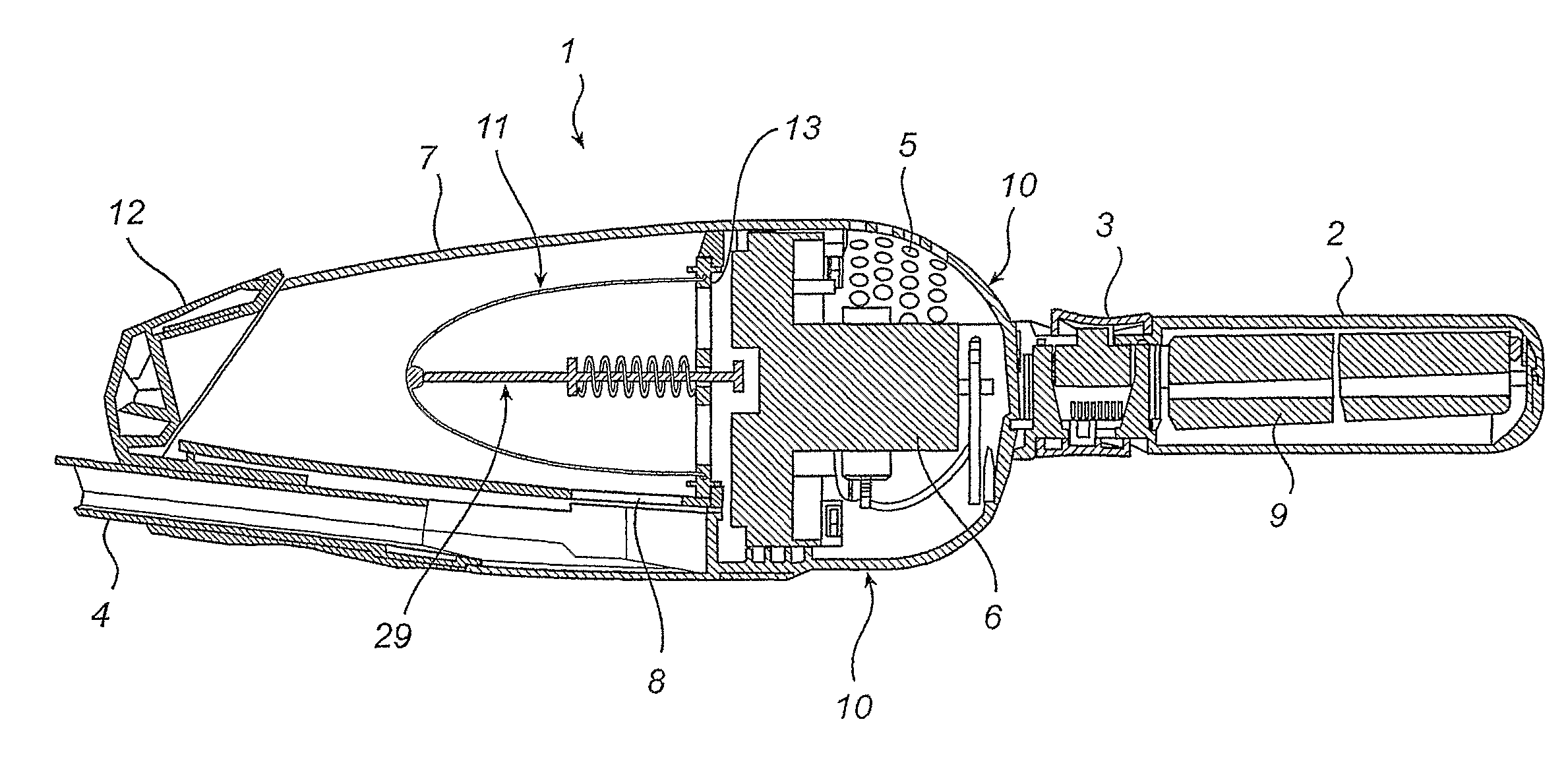
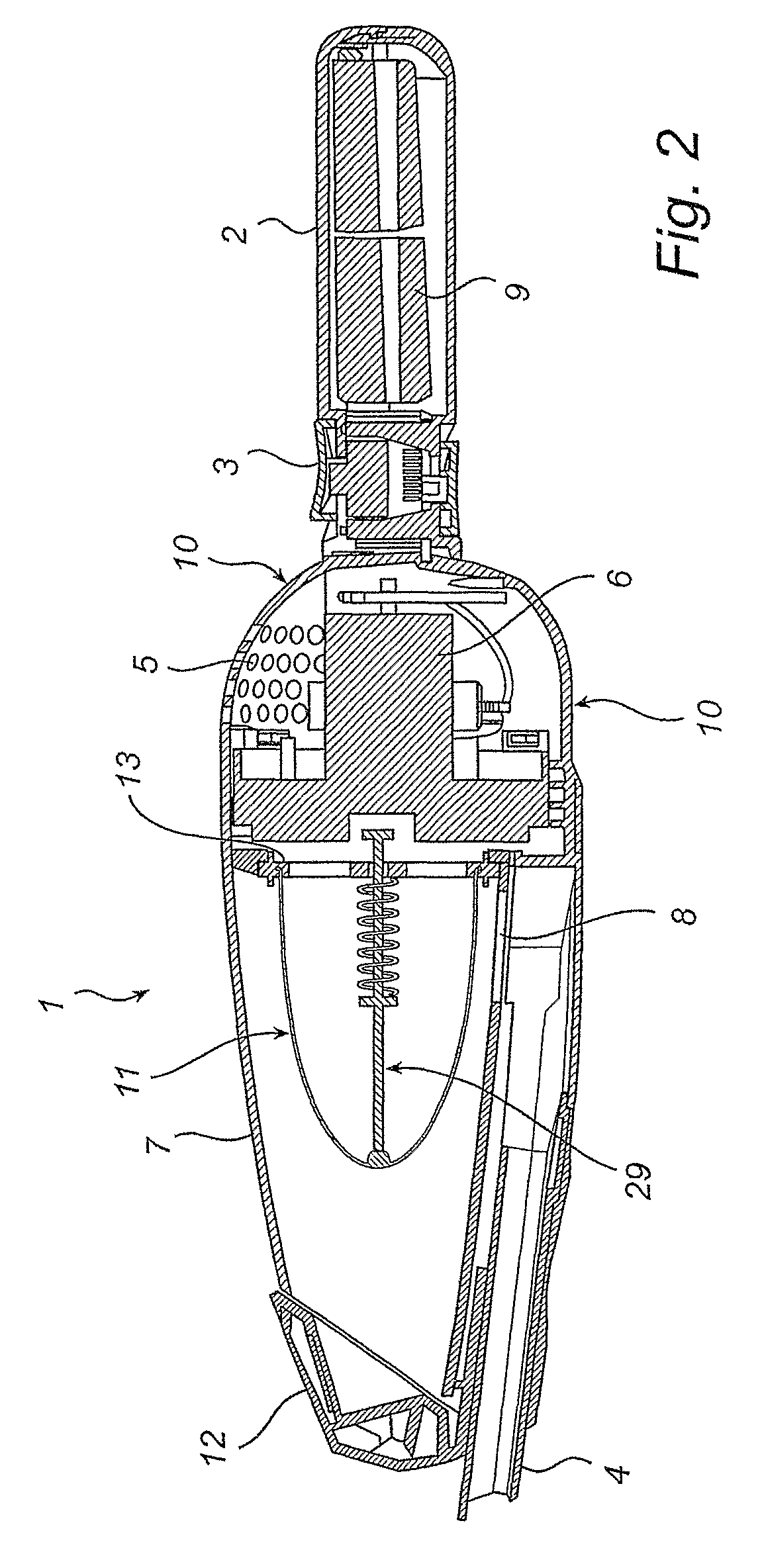
[0035]With reference to FIGS. 3 and 4, a filter unit 11 is illustrated. The filter unit 11 comprises an air permeable and flexible filter body 14 having the form of a tubular bag with its open end, or top portion 15, integrated with a filter attachment member 17. A dust removing means 29 comprising a rod 22 and a spring 28 is arranged inside the filter body 14, and an end portion 23 of the rod 22 is connected to a closed portion 16 of the filter body 14. The rod 22 is supported by a support part 18 integrated with the filter attachment member 17 via at least one arm 19. Preferably the support part 18 forms a hole for the rod 22. The filter body 14 is straightened by a biasing force applied by the spring 28 which is arranged around the rod 22 between a rod protrusion 25 and the support part 18 of the attachment member 17.

[0036]The attachment member 17 comprises holes 20 that are configured to receive therethrough corresponding pegs (not shown) that extend from the housing 10 or from...

second embodiment

[0040]With reference to FIG. 6 a filter unit 11 is illustrated. The filter unit 11 comprises an air permeable and flexible fine particle-filter body 32 having the form of a tubular bag with its open end, or top portion 36, integrated with a filter attachment member 17. A flexible cleaning and / or sealing part 33 is attached to a closed portion 34 of the particle-filter body 32. The filter unit 11 further comprises a coarse pre-filter body 30 which has an opening 31 in an end portion, encloses the particle-filter body 32 and is connected to the attachment member 17. It should be noted that the coarse pre-filter body 30 filters large particles such as hair and fibers, while the particle-filter body 32 filters smaller particles that pass through the coarse filter 30.

[0041]Preferably the coarse pre-filter body 30 is detachable from the attachment member 17, and the coarse filter body 30 may incorporate a separate attachment member (not shown) for attachment to any of the attachment memb...

third embodiment

[0045]FIG. 8 illustrates a filter unit 11 according to a The filter unit 11 comprises a spring 37 arranged inside the filter body 14 to support the filter body 14. The spring 37 is at one end connected to a bottom portion 16 of the filter body 14 and is at its other end connected to the attachment member 17. Preferably the spring 37 has a conical shape corresponding to the straightened shape of the filter body 14, as illustrated in the figure. The spring 37“fills” the inner space defined by the filter body walls.

[0046]The rod 22 of the third embodiment may be omitted and replaced by a weight (not shown) arranged in a bottom portion 16 of the filter body 14. In this case the filter unit 11 is to be shaken for contracting and straightening the filter body 14. Such a weight may be used in any combination of the first and second embodiment.

[0047]The spring 37 according to the third embodiment may also be combined with any of the filters according to the first and second embodiment. The...


PUM

PropertyMeasurementUnit
flexibleaaaaaaaaaa
pressure dropaaaaaaaaaa
vacuum cleaning efficiencyaaaaaaaaaa

Abstract

A vacuum cleaner having a housing with a dust container having an inlet for dust laden air, a filter unit comprising a flexible filter body, a motor fan unit for generating a flow of air through the inlet and through the filter unit, and a dust removing means configured to agitate the flexible filter body in response to a force applied to the dust removing means.

Description

[0001]The present invention claimes priority to International Application No. PCT / SE2007 / 000334 filed Apr. 10, 2007, which claims priority to Swedish Application No. SE 0600820-5 filed Apr. 10, 2006. The entire disclosures of all of the foregoing are incorporated herein by reference.TECHNICAL FIELD[0002]The present invention relates to a hand held vacuum cleaner comprising a housing, a dust container, a motor fan unit and a filter unit.BACKGROUND ART[0003]Vacuum cleaners are commonly used in households for removing dust and debris from various surfaces, and today it is essential that the vacuum cleaner be easy to use, easy to clean and versatile in respect of fields of application.[0004]Generally, a vacuum cleaner has a filter for removing dust from dust laden air flowing through the vacuum cleaner. After some time of usage dust adheres to the filter surface which leads to a pressure drop and reduced vacuum cleaning efficiency. Thus, cleaning of the filter is necessary to remove the...

Claims


Application Information

Patent Timeline
Patent Type & Authority Patents(United States)
IPC IPC(8): A47L9/10
CPCA47L5/24A47L9/20
Inventor BESKOW, JONASMIEFALK, HAKAN
Owner AB ELECTROLUX
Why Eureka
Try Eureka