
Ventilating tube and stylet system

a ventilating tube and stylet technology, applied in the field of medical devices, can solve the problems of patient brain death, hypoxic brain damage or cardiopulmonary arrest, and patient brain damage, and achieve the effects of reducing the risk of strok

Inactive Publication Date: 2013-04-23
GRAY TERENCE KERNAN +2
View PDF23 Cites 6 Cited by
  • Summary
  • Abstract
  • Description
  • Claims
  • Application Information

AI Technical Summary

Benefits of technology

[0007]It is a further object of this invention to provide such a system and method which operates to rapidly place and secure placement of the endotracheal tube.
[0008]It is a further object of this invention to provide such a system that can be repeatedly positioned into the patient without a need for using another system.
[0017]A filter is used to control the exposure of the elements within the proximal housing to contents which may be expelled into the tracheal tube. If the endotracheal tube is incorrectly placed within the esophagus the contents of the stomach can be expelled into the endotracheal tube. Both liquids and solids can be expelled from the stomach, and if not prevented from reaching the detection element by a filter, can cause the detection element to become inactive or produce unpredictable reactions. It is important to shield the detection element from these unwanted contaminants. In instances where the endotracheal tube is incorrectly positioned within the esophagus, damaging stomach contents may flow through the tube and contaminate the filter. If the filter becomes contaminated with these fluids it will not produce a reliable reading in subsequent ventilation cycles. The filter between the lumen of the proximal housing and the elements contained within the proximal housing is used to protect the sensitive elements from exposure to unwanted fluids or debris. This allows the improved endotracheal tube and stylet system to be reused in the event of a misplaced esophageal intubation where the system can subsequently be properly replaced within the trachea. For example, if the endotracheal tube system is incorrectly placed within the esophagus and unwanted fluid or debris is expelled into or through the system, the sensitive elements within the proximal housing will not be compromised. A medical professional can then reposition the same tracheal tube system and reliably confirm proper placement and ventilation using the uncompromised detection element saving both precious seconds and resources.
[0018]The filter does not prevent unwanted contents from reaching the proximal end of the proximal housing, but protects elements contained within the proximal housing from exposure to contents within the lumen of the endotracheal tube and proximal housing.
[0020]In an embodiment the improved tracheal tube system includes a proximal housing that may contain a heating element to raise the temperature of the inspiratory gas to a desired level and a cooling element to lower the inspiratory gas if desired by the medical professional. Typically, the desired temperature of the inspiratory gas is between 35 and 40 degrees Celsius to match the patient's core body temperature. However, this temperature may be adjusted as desired by the medical professional. It is well documented that there is significant heat loss through breathing systems. In operating rooms across the globe anesthesia providers struggle with the balance of increased fresh inspiratory gas flows into the breathing circuit and the heat loss associated with it. This is because the temperature of the fresh inspiratory gas going to the patient is well below normal body temperature. Once in contact with the patient's airway, there is commonly a significant transfer of heat from the patient's lungs to the gas that is then exhaled out of the body. The cycle repeats itself with every breath. The warming element reduces the difference in temperature between the inspired gas and the patient's body temperature, thereby reducing the heat loss. Additionally, heating of the inspiratory gas may be desired to allow for appropriate ventilation and gas exchange between the inspired gas and the patient's circulatory system. The heating element may heat the inspiratory gas using an exothermic chemical reaction or an electronic heating element. Cooling of the inspiratory gas may be desired to lower the patient's body temperature. The cooling element may cool the inspiratory gas using an endothermic reaction, heat exchange, or electronic heating mechanism.
[0021]Additionally, the improved tracheal tube system may include a moisturizing or demoisturizing element to moisten or dry the inspiratory gas as desired by the medical professional. Per the medical professional's guidance, the humidity of the inspiratory gas can be modified to provide proper ventilation and exchange between the inspired gas and the patient's circulatory system. The moisturizing element can humidify the air by chemical means or by evaporation of a moisturizing fluid. Similarly, a demoisturizing or dehumidifying element can dry the air by chemical means or by capturing moisture from the lumen of the proximal housing. By providing a moisturizing element within the proximal housing, the medical professional can modulate the humidity of the inspired gas while simultaneously ventilating the patient. There is also an added port proximal to the patient just beyond the filter, to provide a connection for a nebulizing apparatus. This would be used in addition to other uses, for allowing administration of nebulized medications.

Problems solved by technology

If a patient is not ventilating or suffers an airway blockage for four minutes and no oxygen can reach the patient, he or she will likely suffer brain damage; if the blockage continues for eight minutes, the patient will likely suffer brain death through either hypoxic brain damage or cardiopulmonary arrest.
This procedure requires many steps and is often met with various obstacles.
If incorrectly positioned within the esophagus, the patient will not receive sufficient, if any, airflow to the lungs.

Method used


Image

  • Ventilating tube and stylet system
  • Ventilating tube and stylet system
  • Ventilating tube and stylet system

Examples


Embodiment Construction

[0031]Aside from the preferred embodiment or embodiments disclosed below, this invention is capable of other embodiments and of being practiced or being carried out in various ways. Thus, it is to be understood that the invention is not limited in its application to the details of construction and the arrangement of components set forth in the following description or illustrated in the drawings. If only one embodiment is described herein, the claims hereof are not to be limited to that embodiment. Moreover, the claims are not to be read restrictively unless there is clear and convincing evidence manifesting a certain exclusion, restriction or disclaimer.

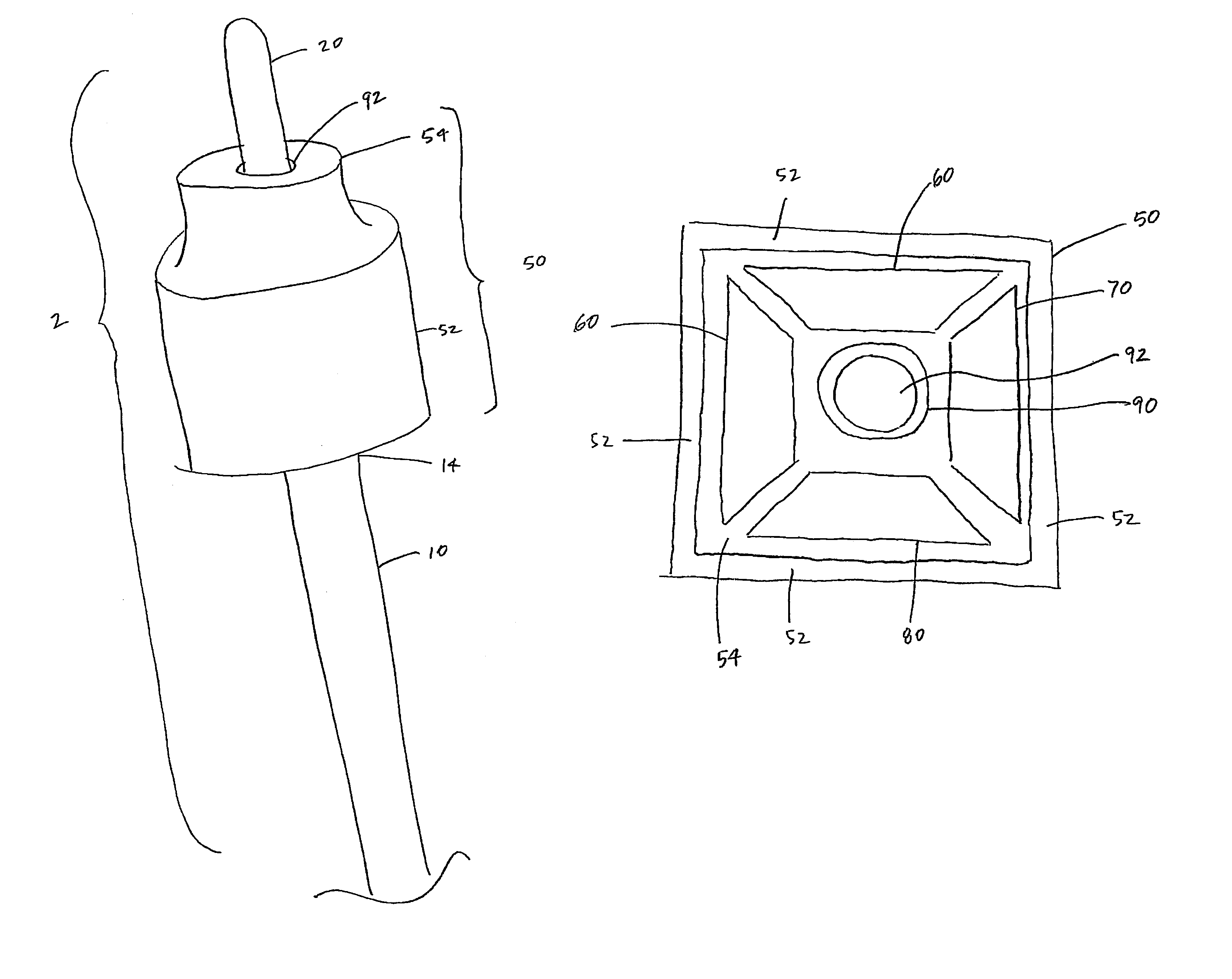
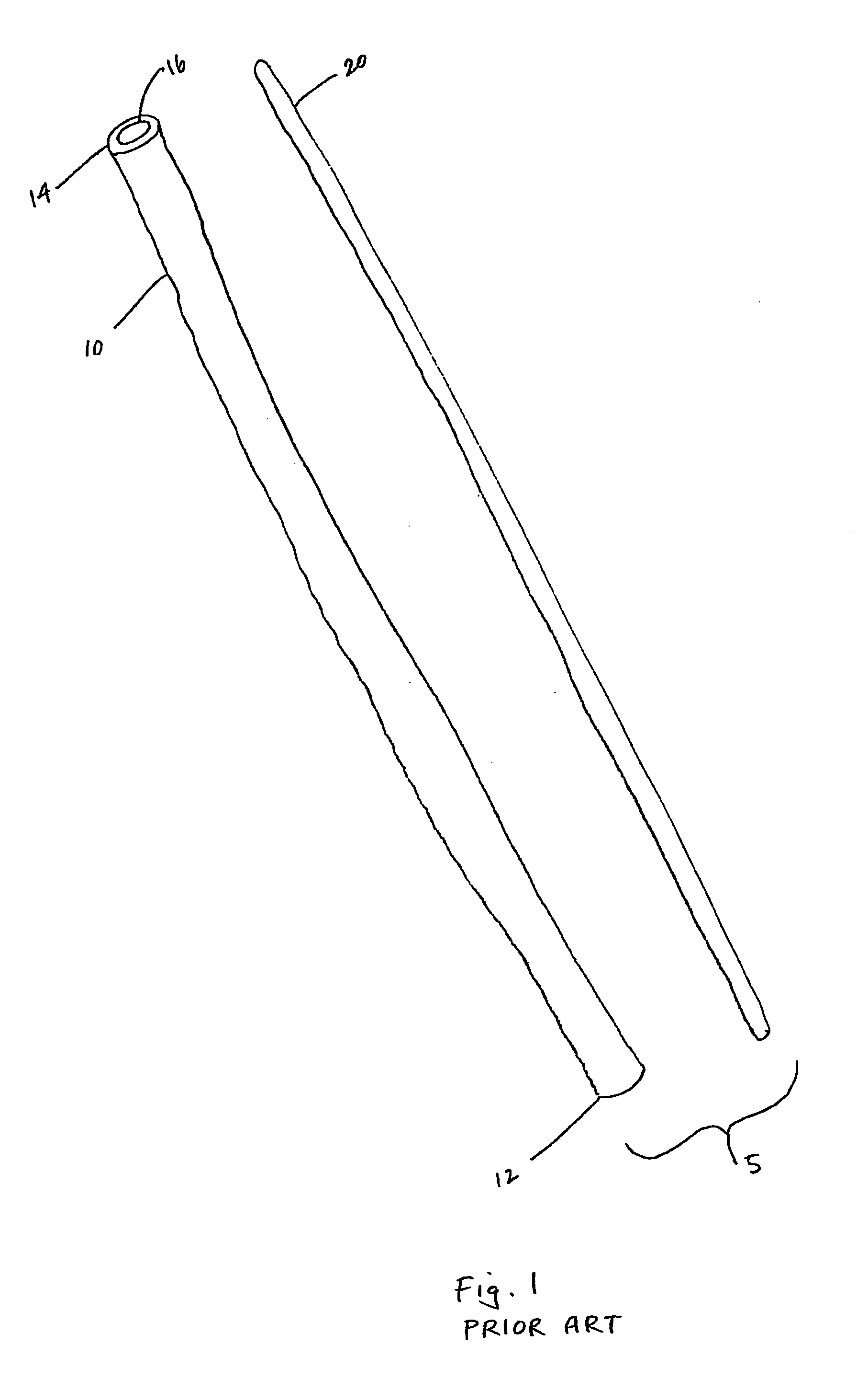
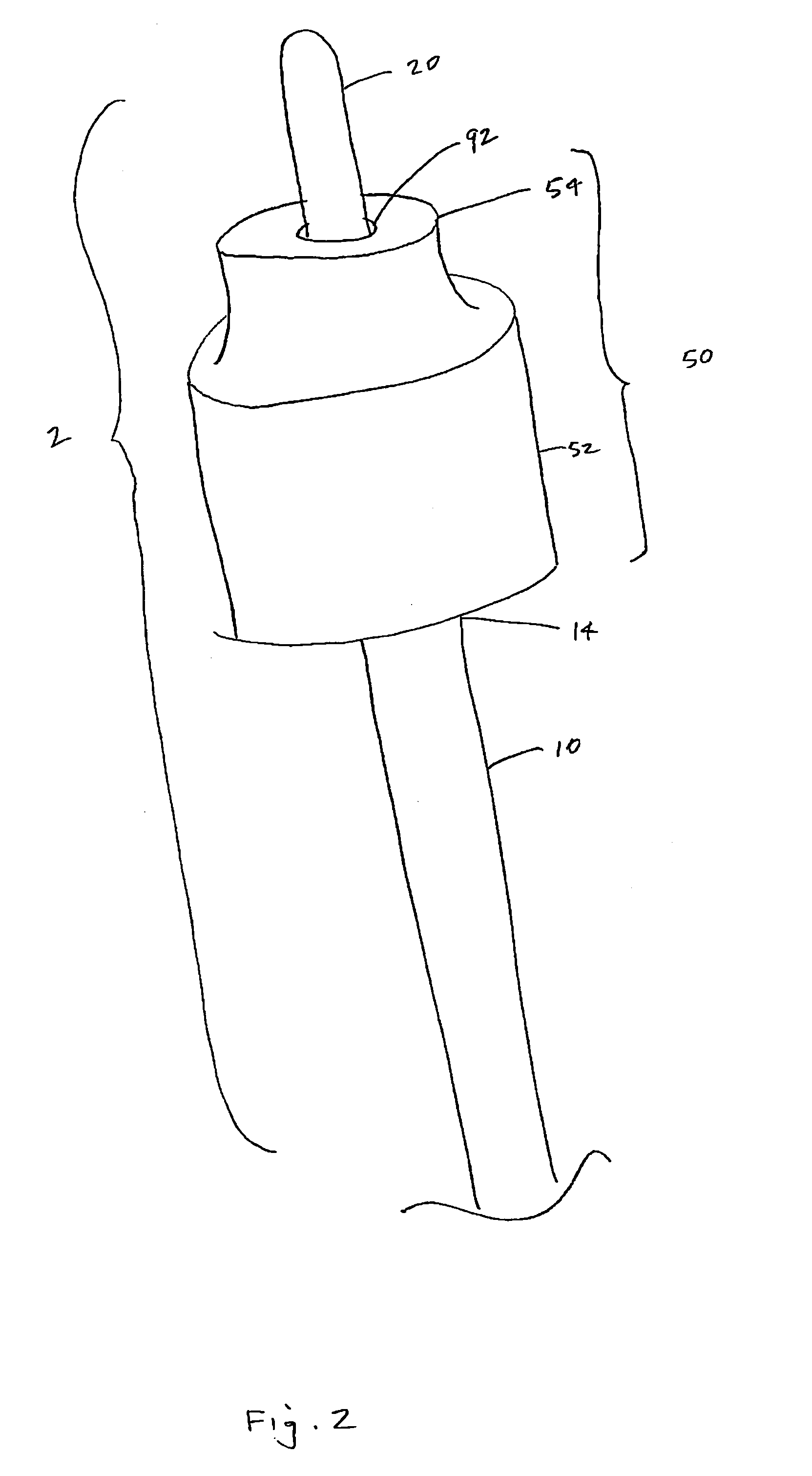
[0032]FIG. 1 shows a schematic of a prior art endotracheal tube system that is typically used by medical professionals to ventilate patients, the system includes an endotracheal tube 10 having lumen 16 that allows gas to flow through endotracheal tube 10. Endotracheal tube 10 has a distal end 12 that is inserted into the patient's a...


PUM


Abstract

A ventilation system and method with a ventilating tube, a stylet removably disposed within the ventilating tube, and a proximal housing. A proximal housing includes a proximal end that connects to the ventilating tube, a distal end that connects to a ventilating machine, a lumen between the proximal end and distal end, an external wall between the proximal end and distal end, a filter contained within the external wall, surrounding the lumen, and connecting the proximal end and distal end, and a cavity between the filter and the external wall. A proximal housing contains at least one detection element and can be sensitive to carbon dioxide. The same proximal housing contains at least one treatment element to heat, cool, humidify, dehumidify, or provide medication to the lumen of the proximal housing.

Description

FIELD OF THE INVENTION[0001]The subject invention relates to medical devices. Specifically, the invention relates to endotracheal ventilating systems.BACKGROUND OF THE INVENTION[0002]Endotracheal tubes are used to provide reliable ventilation and oxygenation to patients with compromised breathing pathways. If a patient is not ventilating or suffers an airway blockage for four minutes and no oxygen can reach the patient, he or she will likely suffer brain damage; if the blockage continues for eight minutes, the patient will likely suffer brain death through either hypoxic brain damage or cardiopulmonary arrest. In cases where the patient's airway is blocked, the time it takes to establish and secure a reliable airway and restore oxygen flow to the patient's lungs is critical.[0003]Endotracheal tube systems are inserted in a patient's airway to provide a conduit to secure a reliable breathing pattern through a secure pathway. In this manner, after either an attempted or successful dir...

Claims


Application Information

Patent Timeline
Patent Type & Authority Patents(United States)
IPC IPC(8): A61M16/16A62B23/02
CPCA61M16/04A61M16/0477A61M16/0488A61M16/1075A61M16/16A61M2016/0413A61M2202/062A61M2205/3606A61M2205/364A61M2205/3653A61M2205/584A61M2205/75A61M16/106A61M2230/432
Inventor GRAY, TERENCE KERNANSICHAU, GARY STEVENCASEY, NIALL PATRICK
Owner GRAY TERENCE KERNAN
Learn More