Ink cartridge for printer

a technology for printers and cartridges, applied in printing and other directions, can solve the problems of deteriorating the printing quality of printed materials, increasing the cost of printing, and increasing the printing cost of printed materials, so as to prevent the generation of excessive positive or negative pressure, increase the internal space, and secure the stable process of discharging ink.

Inactive Publication Date: 2013-04-23
INKTEC CO LTD
View PDF8 Cites 0 Cited by
  • Summary
  • Abstract
  • Description
  • Claims
  • Application Information

AI Technical Summary

Benefits of technology

[0013]According to the present invention, although the sponge is removed from the body, it is possible to constantly maintain the internal pressure of the cartridge as well as to increase an internal space. Further, since there is provided the air suction valve for sucking the air according to the internal pressure of the cartridge, it is possible to previously prevent the ink from being flowed to the outside.
[0014]In addition, since the present invention provides the pressure regulating valve or portion for regulating a difference between the internal pressure and the external pressure of the body, it is possible to prevent the generation of excessive positive or negative pressure in the cartridge.
[0015]Furthermore, since the pressure regulating valve or part is provided at each body of the cartridge, although the plurality of bodies are used to provide multiple color, it is possible to secure the stable process of discharging the ink and to maintain a high printing quality.

Problems solved by technology

Further, since an assembling process for installing the sponge 210 in the body 200 is required additionally, there is another problem that a fabricating cost is increased.
In this case, since it is difficult to maintain an internal pressure of the cartridge constantly, there is a problem that the ink is leaked to the head, thereby deteriorating the printing quality of a printed material.
Thus, there is other problem that the ink is not ejected to the head although the electric signal is input from the controlling part, or the ink is flowed to the head, thereby deteriorating the printing quality of a printed material.

Method used


Image

  • Ink cartridge for printer
  • Ink cartridge for printer
  • Ink cartridge for printer

Examples


first embodiment

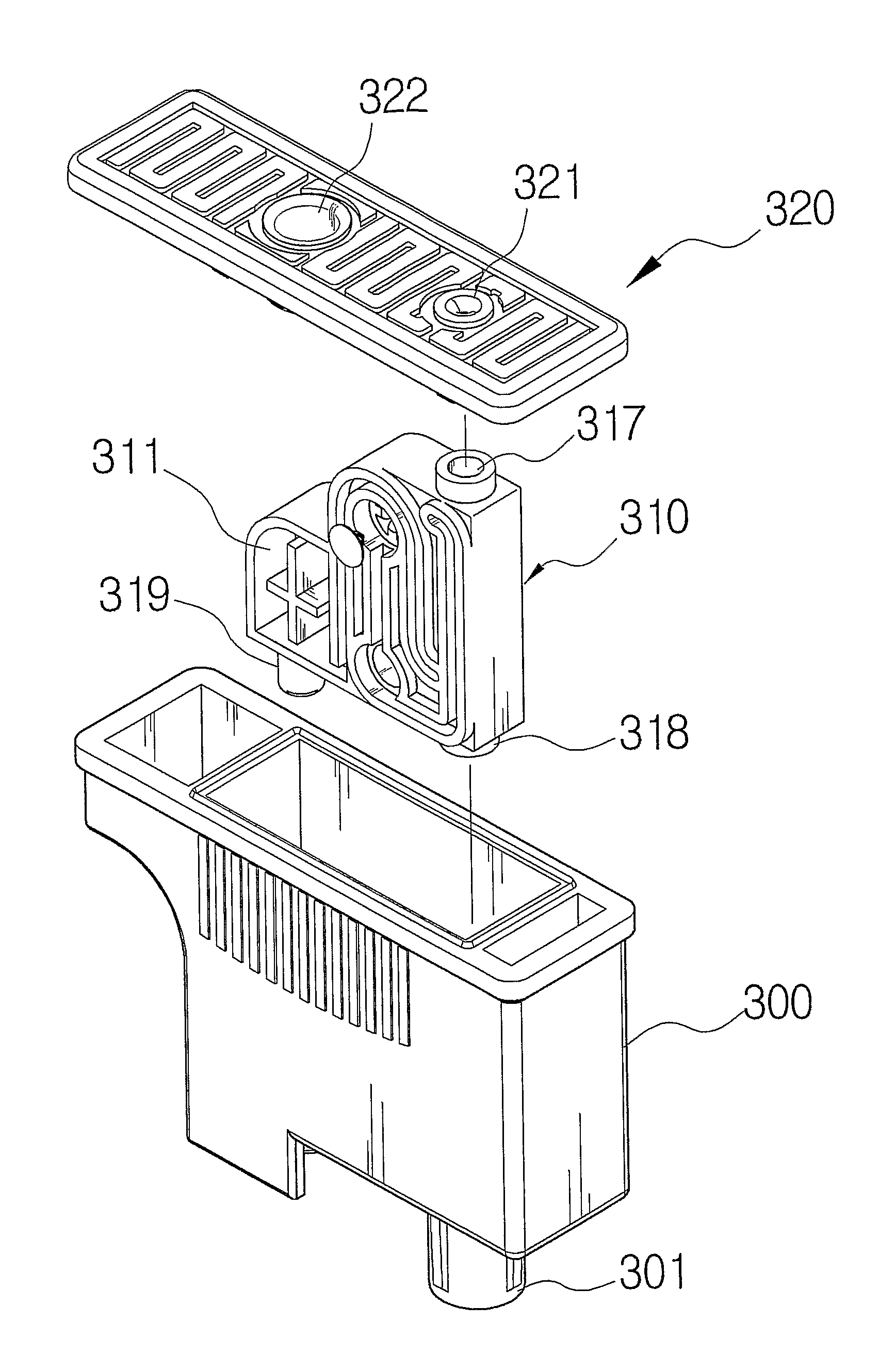
[0046]FIGS. 3 to 11 are views illustrating an ink cartridge according to the present invention, FIGS. 3 and 4 are perspective views, FIG. 5 is a rear view, FIGS. 6 to 9 are a front view, a bottom view, a side view and a top view, respectively, FIG. 10 is an enlarged partial view and FIG. 11 is a cross-sectional view. Of course, various sizes and shapes can be applied to the cartridge of the present invention.

[0047]Referring to FIGS. 3 to 11, the ink cartridge according to an embodiment of the present invention may have predetermined shape one or a plurality of chamber instruments which are arranged side by side in a body 300. At an upper side of the chamber instrument 310, there may be formed an air inducing guide 317. The air inducing guide 317 is communicated with an air inducing port 321 which may be formed at a cover 320. At a lower side of the chamber instrument 310, there is formed a discharging chamber 312. The discharging chamber 312 is coupled to the body 300 to be communic...

second embodiment

[0060]As shown in drawings, the ink cartridge according to the present invention includes the chamber instrument 410 having a predetermined size, the filling chamber 411 for storing the ink and the discharging chamber 412 for discharging the ink. The filling chamber 411 and the discharging chamber 412 are formed at one side of the chamber instrument 410 so as to be communicated with each other through the ink transferring channel 413.

[0061]In the second embodiment of the present invention, a pressure regulating portion 430 of the cover 420 has a function corresponding to the pressure regulating valve 316 of the first embodiment. In the cover 420, the air inducing port 421 communicated with the air inducing guide 417 of the chamber instrument 410 is formed at one side thereof, and the pressure regulating portion 430 having a plurality of air floating hole 432 is formed at a middle portion thereof, and the ink filling portion 422 is formed at the other side thereof.

[0062]If a temperat...


PUM


Abstract

Disclosed is an ink cartridge for a printer, comprising a body having an opened surface and a predetermined shape to receive ink therein; a cover coupled with the body to define a desired space; and a chamber instrument comprising a filling chamber having a space for receiving a part of the ink in the body, a discharging chamber connected with the filling chamber, an ink transferring channel for moving the ink received in the filling chamber to the discharging chamber, an air guiding hold for guiding air to an inside of the cartridge, an air suction valve for selectively passing the guided air and a pressure regulating valve for regulating an internal pressure of the body.

Description

TECHNICAL FIELD[0001]The present invention relates to an ink cartridge for a printer, and more particularly, to an ink cartridge for a printer, in which a body for storing ink is enlarged and an internal pressure of the ink cartridge is maintained constantly, thereby obtaining a high printing quality.BACKGROUND ART[0002]Generally, a printer is to output various documents and pictures prepared by a computer, and classified into a dot printer, an inject printer and a laser beam printer and so on. As shown in FIG. 1, the inkjet printer includes a cartridge carrier 110 which is movably disposed at an inner side of the printer 100, a body for removably installing an ink cartridge 120 which is filled with ink, and a needle 111 for sucking the ink in the ink cartridge 120. Therefore, the ink is transferred through the needle 111 to a head 112 for ejecting the ink.[0003]The ink cartridge may have various shapes and structures according to its kind, but generally has a predetermined shape so...

Claims


Application Information

Patent Timeline
Patent Type & Authority Patents(United States)
IPC IPC(8): B41J2/17B41J2/175
CPCB41J2/17513B41J2/17556B41J2/17553
Inventor CHUNG, KWANG-CHOONYU, CHANG SOOCHO, NAM BOOSHIN, YOUNG CHULHEO, BAEK SONGKIM, IN-HACHOI, JAE-WON
Owner INKTEC CO LTD
Why Eureka
Try Eureka