Component assembly

a technology of components and components, applied in the field of enclosures of portable computing devices, can solve the problems of user dissatisfaction, damage to some internal components (such as printed circuit boards) of portable devices, and complicate the housing design, so as to achieve the effect of substantially reducing the risk of deformation or damage to the housing

Active Publication Date: 2013-04-30
APPLE INC
View PDF78 Cites 19 Cited by
  • Summary
  • Abstract
  • Description
  • Claims
  • Application Information

AI Technical Summary

Benefits of technology

[0017]In one aspect, the steps can be machined in one set up using computer numerical controlled (CNC) machine tools and associated techniques. In addition, any sharp edges can be rounded to a more benign shape thereby reducing any possibility of damaging internal components.
[0019]In another embodiment, a button assembly is described that includes at least a button body including an exterior surface and at least one post extending from a interior surface opposite the exterior surface, the at least one post having a stem portion proximal to the interior surface and a capture portion distal to the interior surface, the capture portion having a diameter greater than the stem portion, a structural support section having a first opening wider than the capture portion of the post of the button body and configured to provide structural stability to a section of a housing to which the structural support section is mounted, the section of the housing having a second opening larger than the exterior surface of the button body, and a retention bracket having a third opening wider than the diameter of the stem portion and narrower than the diameter of the capture portion of the post. In the described embodiment, the button assembly can be at least partially assembled by extending the post of the button body through the second opening in the housing and the first opening in the structural support section and retained in position by the retention bracket.
[0021]In one aspect, an integrated beam system can be formed by removing less than the determined amounts of material from an inner surface of the housing. The integrated beam system can be part of the housing and be used to provide support for the housing by, in part, distributing a force applied to the portable computing device. In this way, by distributing the applied force, the risk of deforming or damaging the housing can be substantially reduced.

Problems solved by technology

The trend of smaller, lighter and powerful presents a continuing design challenge in the design of some components of the portable computing devices.
One design challenge associated with the portable computing device is the design of the enclosures used to house the various internal components.
This design challenge generally arises from a number conflicting design goals that includes the desirability of making the enclosure lighter and thinner, the desirability of making the enclosure stronger and making the enclosure more esthetically pleasing.
Unfortunately, however, the increased weight consistent with the more rugged enclosure can lead to user dissatisfaction whereas bowing of enclosures formed of lightweight material can result in damaging some of the internal components (such as printed circuit boards) of the portable device.
These assembly techniques typically complicate the housing design and create aesthetic difficulties because of undesirable cracks, seams, gaps or breaks at the mating surfaces and fasteners located along the surfaces of the housing.
Moreover, the various components and complicated processes used to manufacture the portable device can make assembly a time consuming and cumbersome process requiring, for example, a highly trained assembly operator working with special tools.
Another challenge is related to techniques for mounting structures within the portable computing devices.
This methodology suffers from the same drawbacks as mentioned above, i.e., assembly is a time consuming and cumbersome process.

Method used


Image

  • Component assembly
  • Component assembly
  • Component assembly

Examples


Embodiment Construction

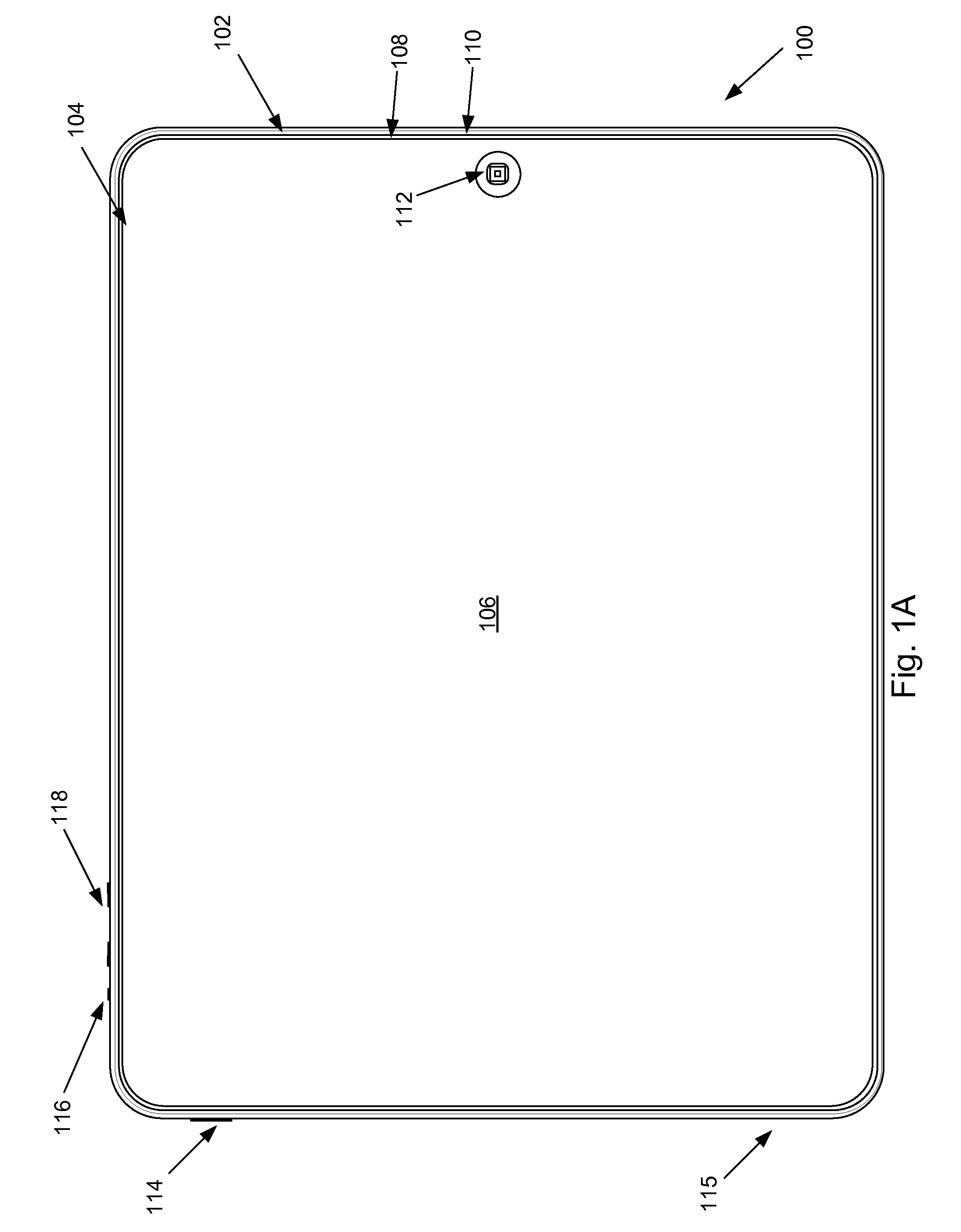
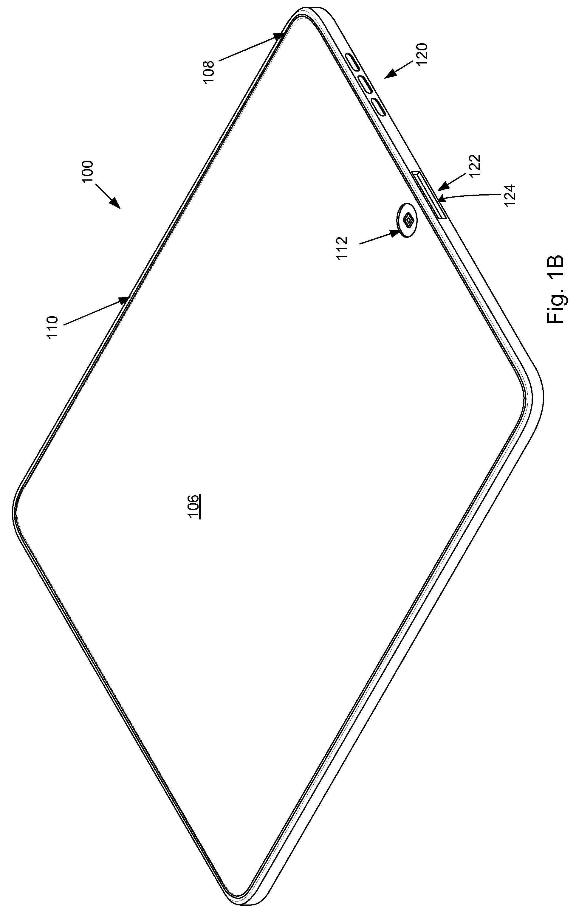
[0009]The described embodiments relate generally to portable computing devices such as laptop computers, tablet computers, and the like. More particularly, enclosures of portable computing devices and methods of assembling portable computing devices are described.

[0010]2. Description of the Related Art

[0011]In recent years, portable computing devices such as laptops, PDAs, media players, cellular phones, etc., have become small, light and powerful. One factor contributing to this reduction in size can be attributed to the manufacturer's ability to fabricate various components of these devices in smaller and smaller sizes while in most cases increasing the power and or operating speed of such components. The trend of smaller, lighter and powerful presents a continuing design challenge in the design of some components of the portable computing devices.

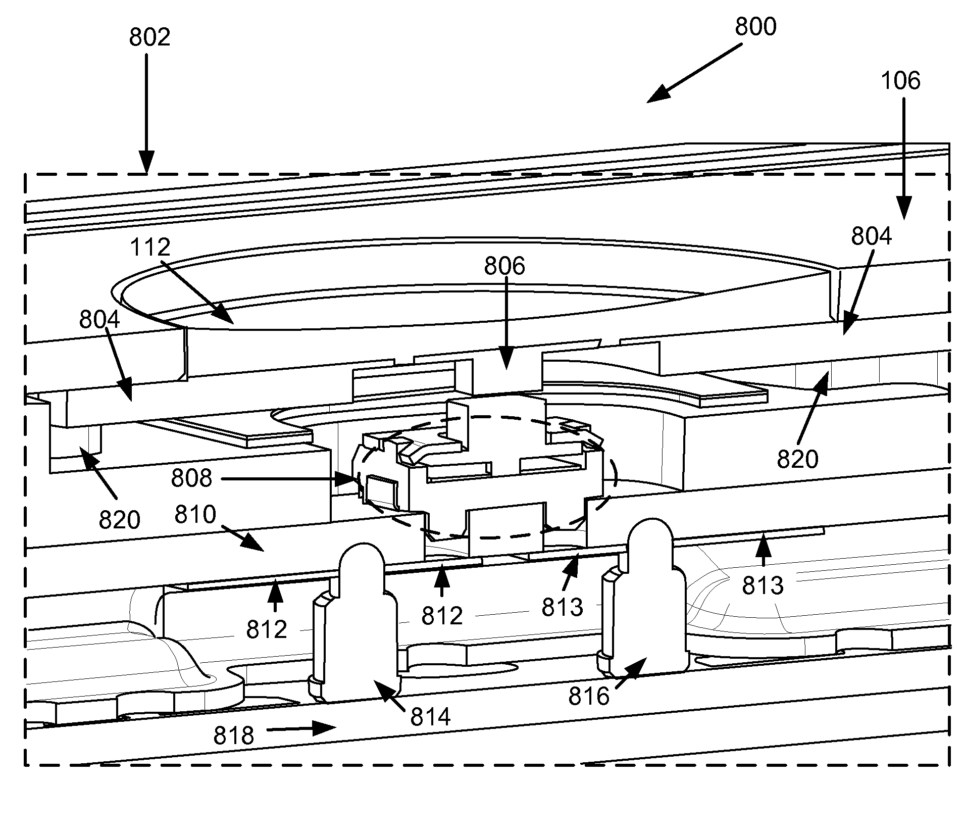
[0012]One design challenge associated with the portable computing device is the design of the enclosures used to house the various inte...


PUM

PropertyMeasurementUnit
thicknessaaaaaaaaaa
thickness tnomaaaaaaaaaa
thickness tminaaaaaaaaaa

Abstract

A portable computing device is disclosed. The portable computing device can take many forms such as a laptop computer, a tablet computer, and so on. The portable computing device can include at least a single piece housing. The single piece housing including a plurality of steps. The plurality of mounting steps are formed by at least removing a preselected amount of housing material at predetermined locations on the interior surface. At least some of the mounting steps are used to mount at least some of the plurality of internal operating components to the housing.

Description

CROSS REFERENCE TO RELATED APPLICATIONS[0001]This patent application claims priority under 35 U.S.C. §119(e) to U.S. Provisional Patent Application Ser. No. 61 / 292,739 entitled “HANDHELD COMPUTING DEVICE” by Ternus et al. filed Jan. 6, 2010 which is incorporated by reference in its entirety for all purposes.[0002]This patent application is related to and incorporates by reference in their entirety the following co-pending patent applications:[0003](i) U.S. patent application Ser. No. 12 / 694,162 entitled “ASSEMBLY OF A DISPLAY MODULE” by Ternus et al. filed Jan. 26, 2010;[0004](ii) U.S. patent application Ser. No. 12 / 694,085 entitled “HANDHELD COMPUTING DEVICE” by Ternus et al. filed Jan. 26, 2010;[0005](iii) U.S. patent application Ser. No. 12 / 694,168 entitled “DISPLAY MODULE” by McClure et al. filed Jan. 26, 2010;[0006](iv) U.S. patent application Ser. No. 12 / 694,166 entitled “PRINTED CIRCUIT BOARD” by McClure et al. filed Jan. 26, 2010; and[0007](v) U.S. patent application Ser. No...

Claims


Application Information

Patent Timeline
Patent Type & Authority Patents(United States)
IPC IPC(8): G06F1/16
CPCG06F1/1613G06F1/1626G06F1/1643G06F1/1656H04M1/0277H05K1/0281H05K1/118H01H13/10H04M1/0266H04M1/0252Y10T29/49002H05K1/147G06F1/16G06F1/1635G06F1/1637G06F1/1658G06F1/1698G06F3/0412
Inventor MCCLURE, STEPHEN R.BANKO, JOSHUA D.TERNUS, JOHN P.RAPPOPORT, BENJAMIN M.GIBBS, KEVIN
Owner APPLE INC
Why Eureka
Try Eureka