Orthodontic clasp

a technology of orthodontic clasps and clasps, applied in the field of orthodontic clasps, can solve problems such as considerable time lost in treatment, and achieve the effect of preventing acrylic from breaking and strengthening the structural strength of acryli

Inactive Publication Date: 2013-05-07
HANG WILLIAM M
View PDF22 Cites 0 Cited by
  • Summary
  • Abstract
  • Description
  • Claims
  • Application Information

AI Technical Summary

Benefits of technology

[0005]Applicant's invention comprises an orthodontic clasp which is relatively comfortable for the patient, easy to adjust for optimal retention; and is much more structurally sound than orthodontic clasps presently in use. This new clasp provides an orthodontic appliance, on which it is used, with superior retentive strength. For instance, the Crozat Clasp provides no retention at all if its solder joint breaks, since the clasping part falls off entirely. The orthodontic appliance using the Crozat Clasp will then fall out of the patient's mouth.
[0016]The present invention is a new and useful orthodontic clasp which is a significant advance in the art. This orthodontic clasp, when in use, is anchored to an associated orthodontic appliance and has a clasp weld / solder joint. Should this clasp weld / solder joint fail or break, the orthodontic clasp will maintain its general form and functionality for a matter of days or longer, until said break is repaired, or the orthodontic appliance may be replaced by an orthodontist. This orthodontic clasp is less prone to failure and breakage, easier to adjust by the orthodontist, and is more effective in treating patients if breakage should occur, as there would be little or no interruption in treatment due to the anchoring of the orthodontic clasp in the acrylic portion of its associated orthodontic appliance.
[0019]Two of the four wire bends on an orthodontic clasp form a clasp anchor and these anchors are embedded into the acrylic, as shown in FIGS. 5-8, when the orthodontic clasp is in use. The clasp anchors are preferred to be crimped. The clasp anchors when embedded in the acrylic also serve to reinforce the structural strength of the acrylic, and to prevent the acrylic from breaking, much as rebar is used to reinforce concrete.

Problems solved by technology

Commonly used clasps today do not have this advantage, and there may be considerable time lost in treatment.

Method used


Image

  • Orthodontic clasp
  • Orthodontic clasp
  • Orthodontic clasp

Examples


Embodiment Construction

[0029]There may be some variation in the embodiments of the orthodontic clasp, depending on the patient and the orthodontic appliance used to meet the patient's needs. Most orthodontic appliances will use two orthodontic clasps, but some appliances may use more than two. The preferred embodiment of the orthodontic clasp is that suited for most patients and for most applications of the invention. Some patients have special areas that may require some variation in the orthodontic clasp shape.

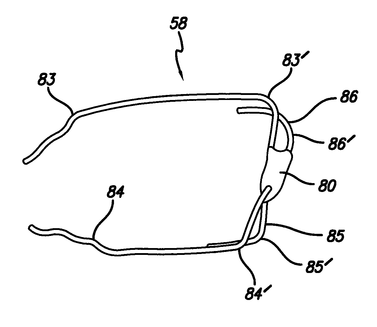
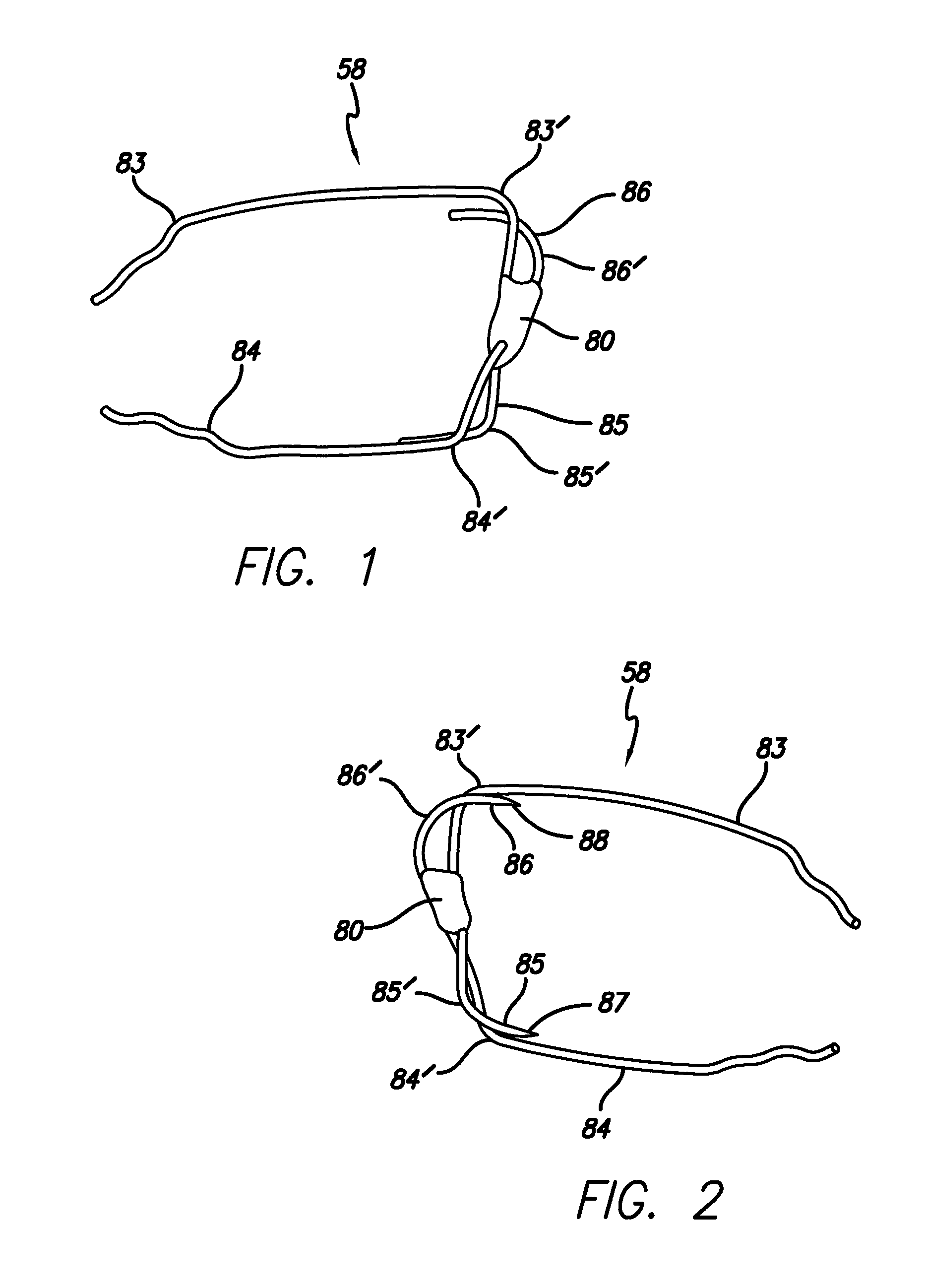
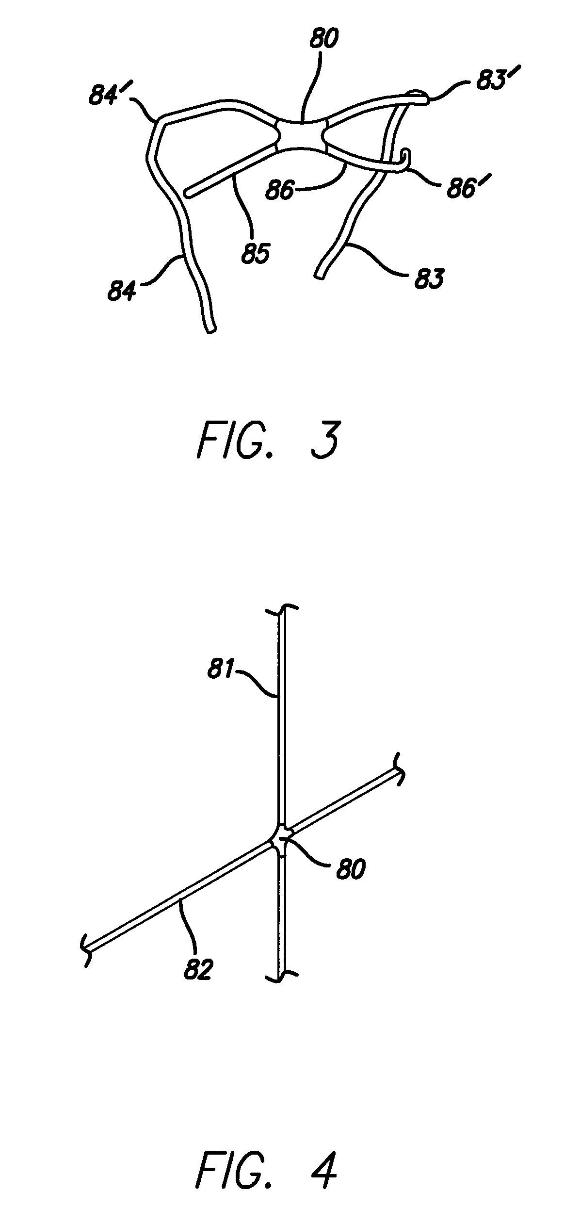
[0030]Referring to FIGS. 1-4, a simple embodiment of the orthodontic clasp is comprised essentially of only the bare essential elements for the simplest embodiment of the invention. A simple embodiment of the orthodontic clasp (58) is comprised essentially of two wires (81, 82) attached at a joint (80) with a weld / solder joint (FIG. 4). The two wires (81, 82) are usually attached at a set of angles of between 20° and 160° and about 60° and 120°, depending upon the needs of the patient. The two att...


PUM


Abstract

A new and useful orthodontic clasp that is more resistant to breakage, and when in use is unlikely to separate from its associated orthodontic appliance should breakage occur, comprising two metal wires crossed at an angle and held together with a weld / solder joint, said weld / solder joint having four wire segments extending from said two metal wires crossed at the weld / solder joint, two of said wire segments adjacent and longer in length and two of said wire segments adjacent and shorter in length, said four wire segments each having a clasp wire bend.

Description

FIELD OF THE INVENTION[0001]This invention relates to a new and useful orthodontic clasp designed for both orthodontic utility and for increased strength and resistance to breakage.BACKGROUND OF THE INVENTION[0002]Heretofore, orthodontic clasps have had a number of associated problems. These problems include, but are not limited to, a design that is uncomfortable for the patient and not easily adjusted for orthodontic treatment, a design that is not structurally sound and resistant to breakage, and a design that does not secure the clasp to the orthodontic appliance should breakage occur.[0003]During the course of orthodontic treatment, adjustments to the orthodontic appliance are routinely made for treatment to progress. A commonly used clasp is known at the Crozat Clasp, which has a significant chance of breakage when adjustments are made using pliers, the instrument of choice for making such adjustments.[0004]Another clasp, known as the Adams Clasp, is commonly used in removable ...

Claims


Application Information

Patent Timeline
Patent Type & Authority Patents(United States)
IPC IPC(8): A61C3/00
CPCA61C7/00A61C7/10
Inventor HANG, WILLIAM M.
Owner HANG WILLIAM M
Why Eureka
Try Eureka