Multi-directional torsional hysteretic damper (MTHD)

a hysteretic damper and multi-directional technology, applied in the direction of shock-proofing, mechanical equipment, building components, etc., can solve problems such as large damping

Inactive Publication Date: 2013-05-14
DICLELI MURAT +1
View PDF11 Cites 3 Cited by
  • Summary
  • Abstract
  • Description
  • Claims
  • Application Information

AI Technical Summary

Problems solved by technology

Dampers are energy dissipaters.
Although the shock absorbing mounting can possesses slight damping, it is not a hysteretic damper and as being a self-centering system, it cannot have a large damping.

Method used


Image

  • Multi-directional torsional hysteretic damper (MTHD)
  • Multi-directional torsional hysteretic damper (MTHD)
  • Multi-directional torsional hysteretic damper (MTHD)

Examples


Embodiment Construction

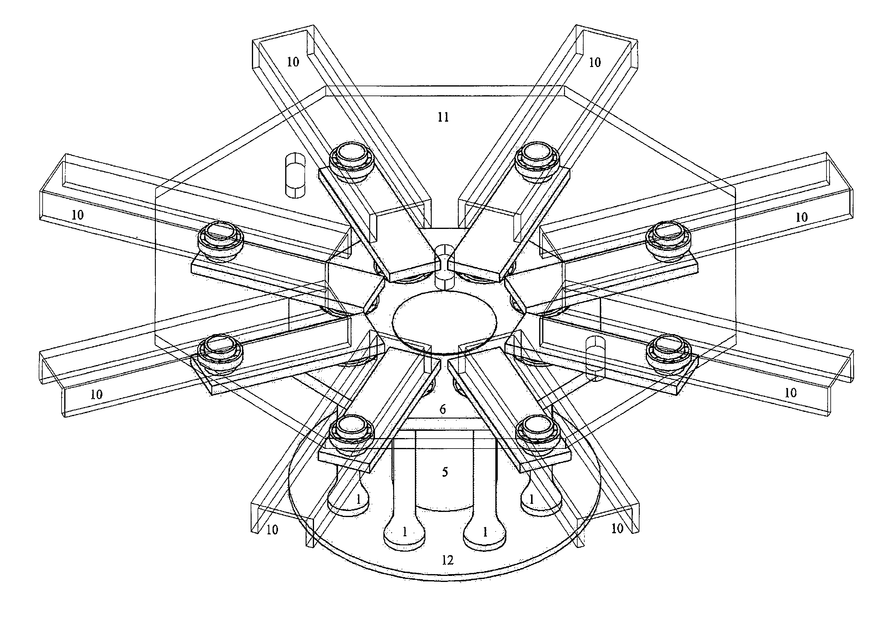
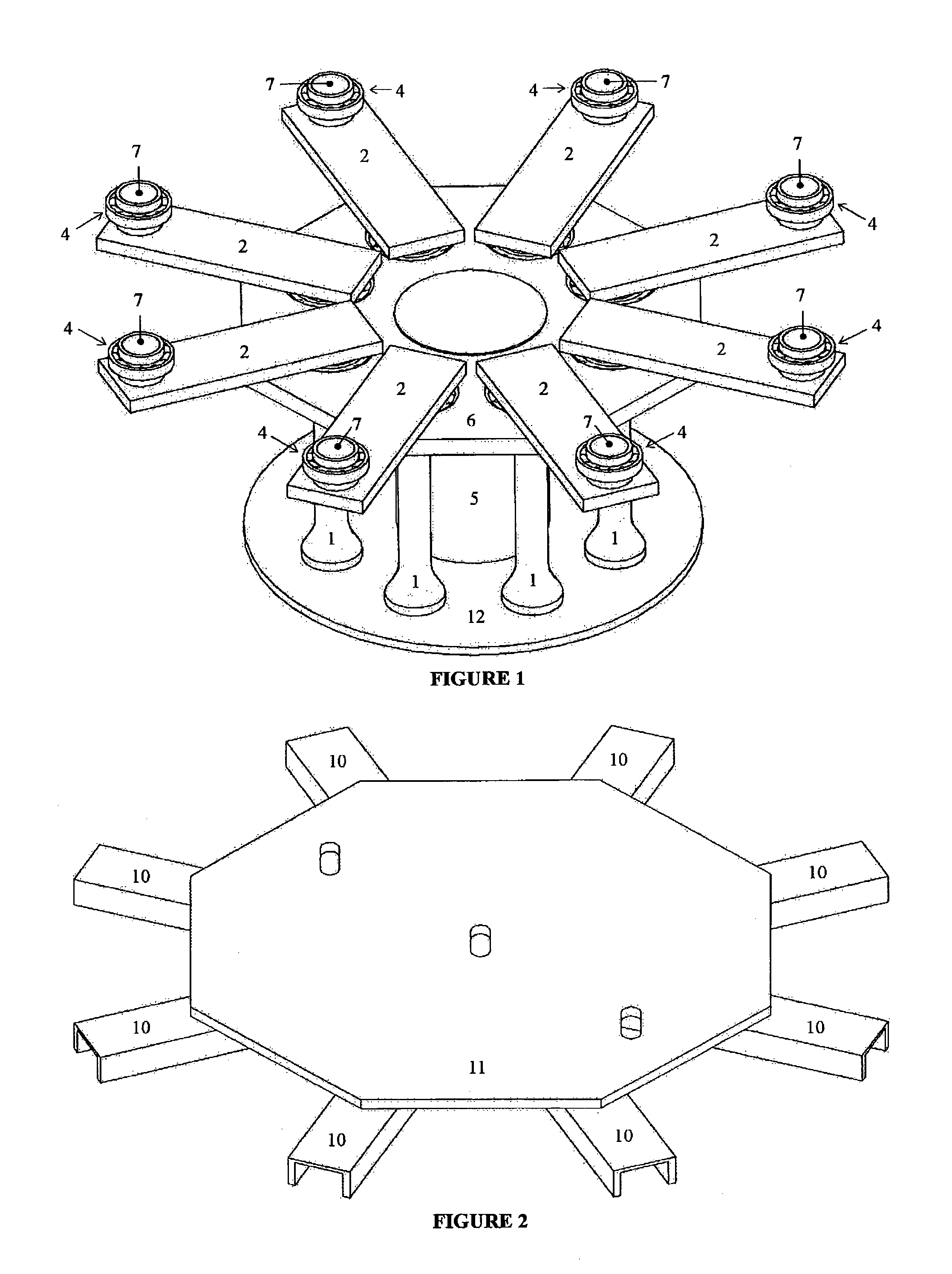
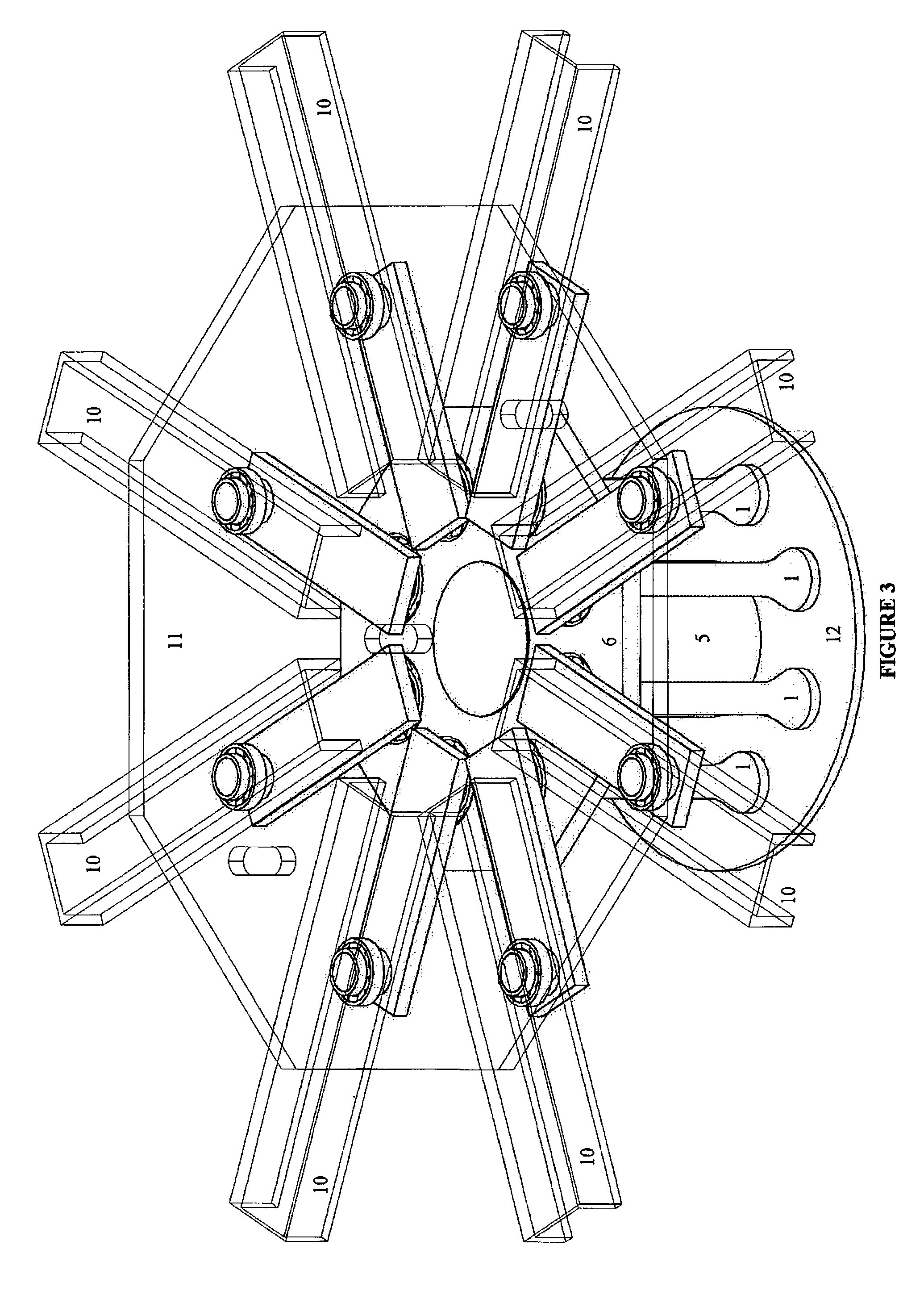
[0044]The said hysteretic damper device related to the present invention consists of three main parts;[0045]1. The Yielding Core: Along with the arm assembly which includes a steel ball bearing (4) to create a roller hinge type connection between the arm (2) and the rail system and allow for frictionless movement of the arm (2) end inside the rail (10). The arm (2) is welded to the yielding core (1) on one end (at top) and in the other end has a cylindrical solid shaft (7) welded to it which serves as a mounting axis for the arm ball bearing (4), all shown in FIG. 9. There are also two rings (8, 9) on the top and bottom sides of the arm ball bearing (4) to fix it in place. Also any other type of attachment such as a pin can be used instead of upper and bottom hollow cylindrical rings (8, 9). The upper ring (8) is welded to the mounting shaft (7). The yielding cores (1) are energy dissipation elements of the said hysteretic damper of the present invention and are made of steel. At le...


PUM


Abstract

The invention relates to seismic protection (anti-seismic) devices and, in particular, to seismic hysteretic dampers, used to protect the structures against severe earthquakes. These devices are installed at points where large displacements are expected due to earthquake shakings, such as between a bridge deck and bearing points of said bridge (e.g. the pier cap beam).

Description

RELATED FIELD OF THE INVENTION[0001]The invention relates to seismic resistant (anti-seismic) devices and, in particular, to seismic hysteretic dampers, used to protect the structures against severe earthquakes. These devices are installed at points where large displacements is are expected due to earthquake shakings, such as between the bridge deck and bearing points (pier cap beam).BACKGROUND OF THE INVENTIONPrior Art[0002]Dampers are energy dissipaters. They dissipate the kinetic energy swept into them due to the relative motion of two (mounting) ends. Speaking in terms of force-displacement rather than energy, they work by exerting a force upon their moving ends which always opposes the relative displacement of two ends. We shall call this force that can be used as a measure of energy dissipation capacity of the damper, the ‘reaction force’ of the damper. In hysteretic dampers such property is achieved by utilizing the hysteretic behavior in metals.[0003]The available multi-dire...

Claims


Application Information

Patent Timeline
Patent Type & Authority Patents(United States)
IPC IPC(8): E04B1/98E04H9/02
CPCE04H9/021F16F15/063E01D19/043
Inventor DICLELI, MURATSALEM MILANI, ALI
Owner DICLELI MURAT
Why Eureka
Try Eureka