
Flicker detection circuit for imaging sensors that employ rolling shutters

a detection circuit and imaging sensor technology, applied in the field of flicker detection circuits, can solve problems such as image flicker that is caused, non-stationary sequences posing a challenging problem for multi-frame process, spatial flicker generation in images under fluorescent lighting,

Active Publication Date: 2013-05-14
ATI TECH INC
View PDF15 Cites 4 Cited by
  • Summary
  • Abstract
  • Description
  • Claims
  • Application Information

AI Technical Summary

Benefits of technology

The patent describes a solution for detecting and reducing flickering in images captured by digital cameras. The technology involves comparing frames of video or images to detect any misalignment between them. If misalignment is detected, the technology realigns the frames and uses the resulting data to determine if there is any flickering present. If flickering is detected, the technology adjusts exposure settings to reduce flickering. This can be done during preview mode or at any other suitable time. Overall, this technology improves image quality and reduces flickering in photos and videos captured by digital cameras.

Problems solved by technology

One of the challenges of this technology is the image flicker that is caused by the interaction of fluorescent lighting and the sensor's electronic rolling shutter.
Non stationary sequences pose a challenging problem to multi frame processes.
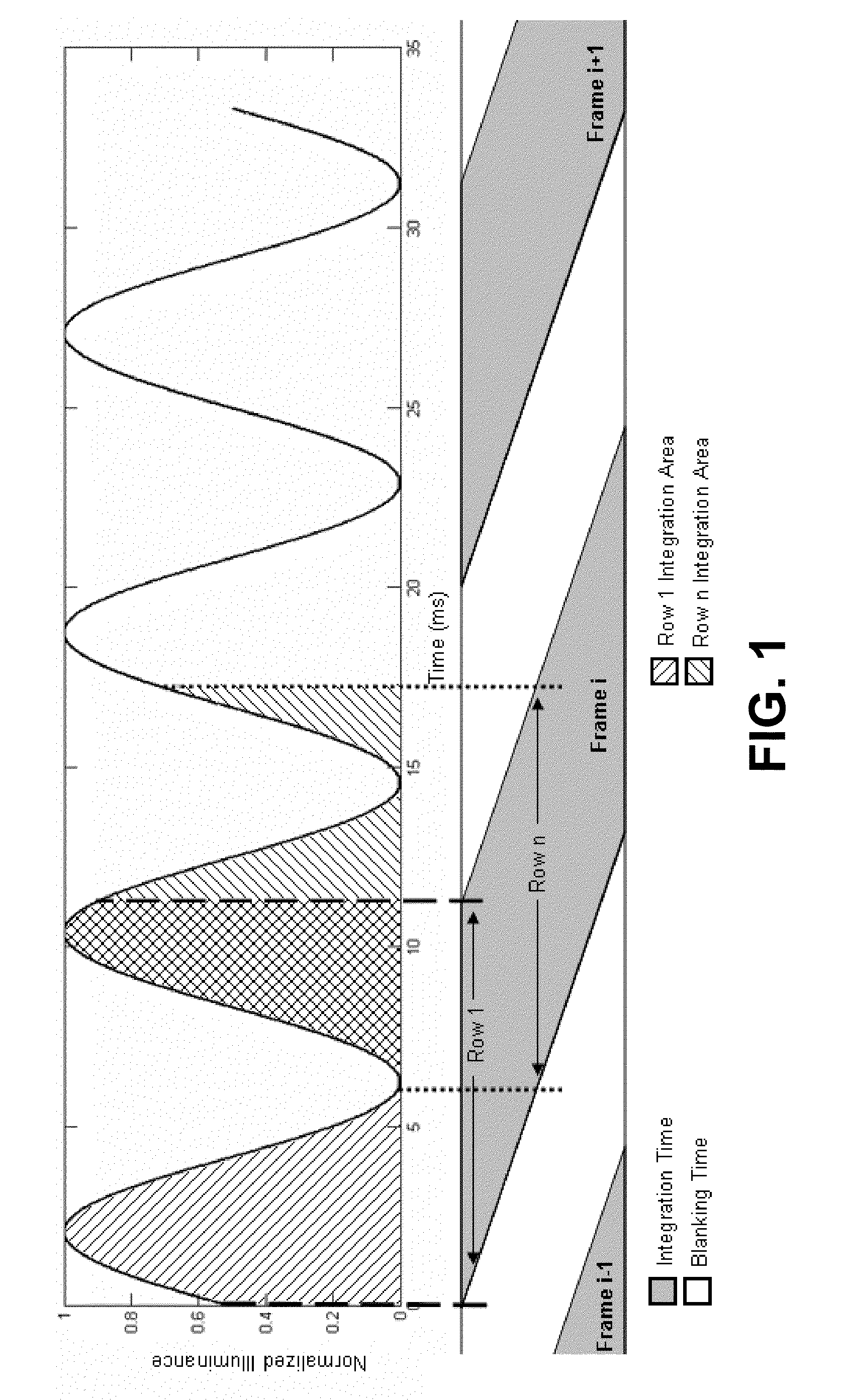
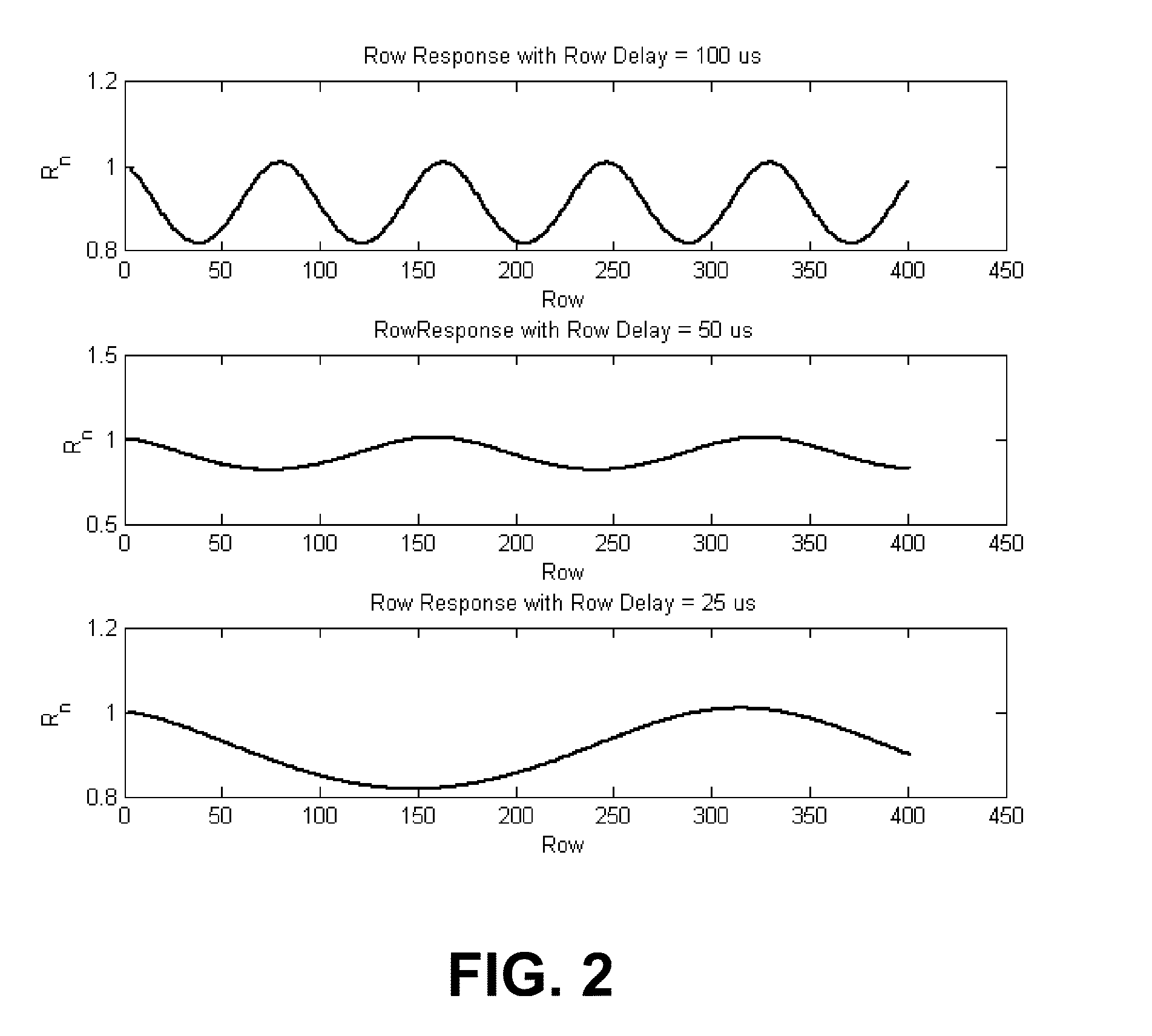
One consequence of this approach is that spatial flicker is generated in the image under fluorescent lighting since each row is exposed to a different amount of total illuminance.
A real time imaging system places additional constraints on flicker detection.
Practical imaging systems need to operate at 15 or 30 fps which greatly reduces the spatial flicker frequencies in the image making the detection process more challenging.
One of the significant challenges of a real time flicker detection system is the low spatial frequency of the flicker in an image.
The results were obtained using static scenes and did not consider more practical cases were the scene content is dynamic.
However, the above works do not provide a suitable flicker detection and correction scheme for imaging sensor that employ a rolling shutter configuration.

Method used


Image

  • Flicker detection circuit for imaging sensors that employ rolling shutters
  • Flicker detection circuit for imaging sensors that employ rolling shutters
  • Flicker detection circuit for imaging sensors that employ rolling shutters

Examples


Embodiment Construction

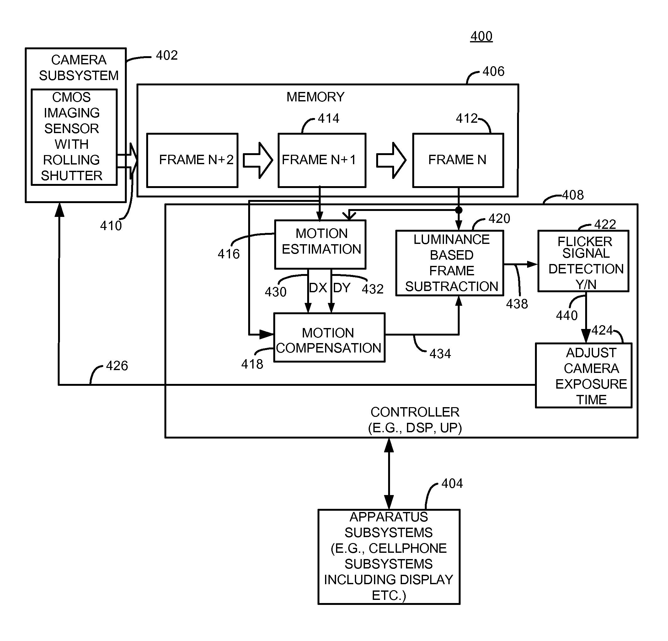
[0043]Briefly, circuitry, apparatus and methods provide flicker detection and improved image generation for digital cameras that employ image sensors. In one example, circuitry and methods are operative to compare a first captured frame with a second captured frame that may be, for example, sequential and consecutive or non-consecutive if desired, to determine misalignment of scene content between the frames. A realigned second frame is produced by realigning the second frame with the first frame if the frames are determined to be misaligned. Luminance data from the realigned second frame and luminance data from the pixels of the first frame are used to determine if an undesired flicker condition exists. If an undesired flicker condition is detected, exposure time control information is generated for output to the imaging sensor that captured the frame, to reduce flicker. This operation may be done, for example, during a preview mode for a digital camera, or may be performed at any ...


PUM


Abstract

Circuitry, apparatus and methods provide flicker detection and improved image generation for digital cameras that employ image sensors. In one example, circuitry and methods are operative to compare a first captured frame with a second captured frame that may be, for example, sequential and consecutive or non-consecutive if desired, to determine misalignment of scene content between the frames. A realigned second frame is produced by realigning the second frame with the first frame if the frames are determined to be misaligned. Luminance data from the realigned second frame and luminance data from the pixels of the first frame are used to determine if an undesired flicker condition exists. If an undesired flicker condition is detected, exposure time control information is generated for output to the imaging sensor that captured the frame, to reduce flicker. This operation may be done, for example, during a preview mode for a digital camera, or may be performed at any other suitable time.

Description

CROSS-REFERENCE TO RELATED APPLICATION[0001]The present patent application claims priority from and the benefit of U.S. Provisional Patent Application No. 61 / 114,748 filed Nov. 14, 2008, entitled FLICKER DETECTION CIRCUIT FOR IMAGING SENSORS THAT EMPLOY ROLLING SHUTTERS, which is hereby incorporated herein by reference in its entirety.FIELD OF THE DISCLOSURE[0002]The disclosure relates generally to flicker detection circuits and devices employing the same.BACKGROUND OF THE DISCLOSURE[0003]CMOS imaging sensors are commonplace in many handheld devices. One of the challenges of this technology is the image flicker that is caused by the interaction of fluorescent lighting and the sensor's electronic rolling shutter. Non stationary sequences pose a challenging problem to multi frame processes. To address these limitations a new process is proposed to improve flicker detection performance by using frame alignment. This method significantly improves the performance in handshake and vertica...

Claims


Application Information

Patent Timeline
Patent Type & Authority Patents(United States)
IPC IPC(8): H04N9/73H04N3/14H04N25/00H04N23/76
CPCG03B19/18H04N5/23248H04N5/3532H04N5/23267H04N5/2357H04N5/23254H04N23/6811H04N23/68H04N23/683H04N23/745H04N25/531H04N23/73
Inventor GREENLAND, GRAHAM C. H.ALEKSIC, MILIVOJEGOMA, SERGIO
Owner ATI TECH INC
Learn More