
Processing of 3D image information based on texture maps and meshes

a technology of texture maps and image information, applied in the field of representation of three dimensional image data/information using texture maps and meshes, can solve the problems of reducing the number of triangles, reducing the spatial resolution of the mesh, and being less easy to achieve other embodiments, so as to improve the distribution of three dimensional image information, and improve the quality of data rate

Active Publication Date: 2021-11-30
KONINKLJIJKE PHILIPS NV
View PDF16 Cites 0 Cited by
  • Summary
  • Abstract
  • Description
  • Claims
  • Application Information

AI Technical Summary

Benefits of technology

[0022]The invention may provide improved distribution of three dimensional image information in many scenarios. In many embodiments, an improved encoding may be achieved and in particular an improved quality to data rate can be achieved. The approach may in many embodiments allow an improved image to be received from the received 3D information. Further, this may be achieved while typically maintaining relatively low complexity and a high degree of computational efficiency. In particular, the approach may typically support the efficient use of e.g. dedicated, standardized, and optimized hardware. For example, many platforms developed for computer graphics processing may be used to support steps of the processing.
[0059]This may provide a particularly efficient and flexible approach and may result in an improved image generation in many embodiments.

Problems solved by technology

However, as this may be considered inconvenient to the user, it is in many scenarios preferred to use autostereoscopic displays that use means at the display (such as lenticular lenses, or barriers) to separate views, and to send them in different directions where they individually may reach the user's eyes.
This will reduce the number of triangles but also decrease the spatial resolution of the mesh.
Whereas this may be relatively easy to provide in some applications, such as e.g. games based on fully computer generated virtual scenes and environments, it may be less easy in other embodiments.
However, as the input mesh typically is not perfect, such viewpoint transformations may result in quality degradation if the shift is too significant.
However, the input texture map and mesh will in such a case not comprise any information for these de-occluded parts.
Accordingly, they cannot be optimally represented as the required information is not available.
View-synthesis errors and inaccuracies tend to increase with increasing distance of the new shift.
However, this complicates distribution, storage, encoding / decoding, and processing of the data stream.

Method used


Image

  • Processing of 3D image information based on texture maps and meshes
  • Processing of 3D image information based on texture maps and meshes
  • Processing of 3D image information based on texture maps and meshes

Examples


Embodiment Construction

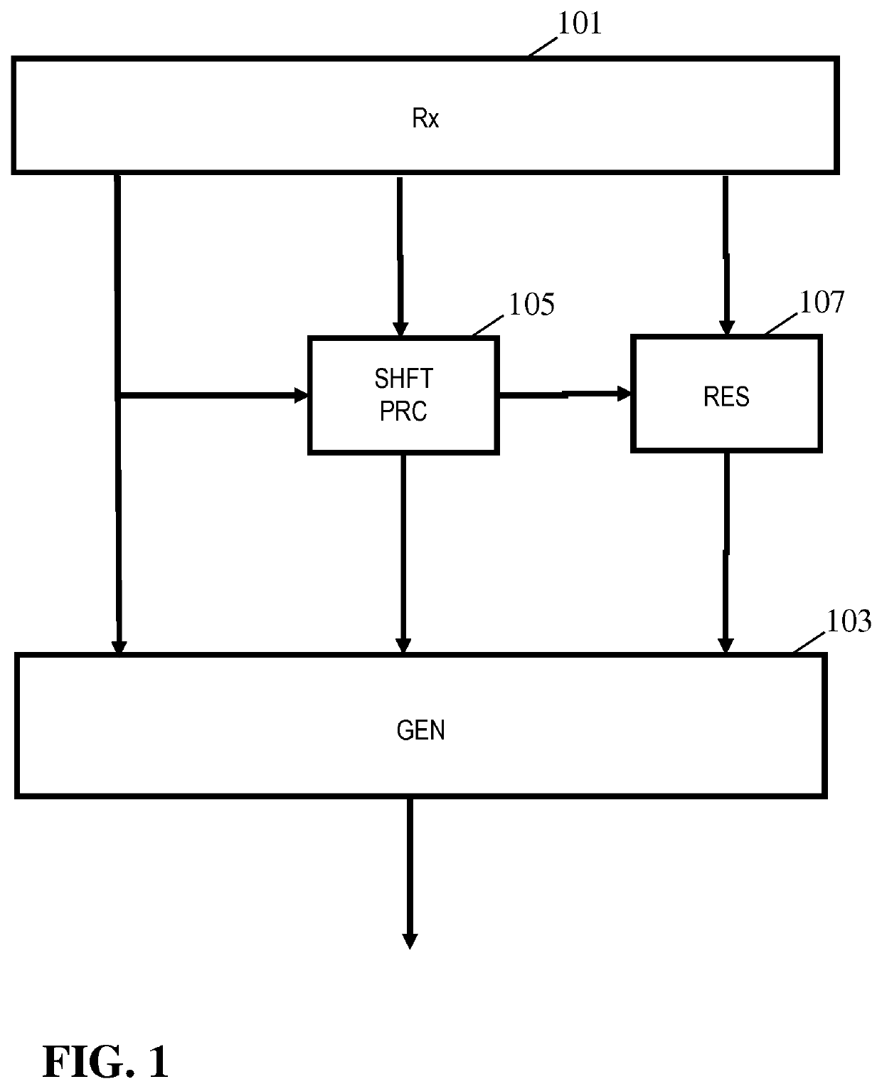
[0075]FIG. 1 illustrates an example of an apparatus for generating a 3D image signal. The apparatus, and indeed the generated image signal, is based on representing 3D information by a texture map and associated depth map. The apparatus may specifically be part of a virtual reality server which may provide an image signal with 3D information for a scene. A (typically remote) virtual reality client may access the virtual reality server and in response be provided with the image signal from which it may locally generate suitable images of the scene to provide the virtual reality experience. Specifically, the virtual reality client device may typically be arranged to generate images for a given desired viewpoint based on the information received from the virtual reality server. Thus, the apparatus of FIG. 1 will henceforth be referred to as the encoder, and specifically as the encoder of a virtual reality server, but it will be appreciated that this is not intended to imply a limitatio...


PUM


Abstract

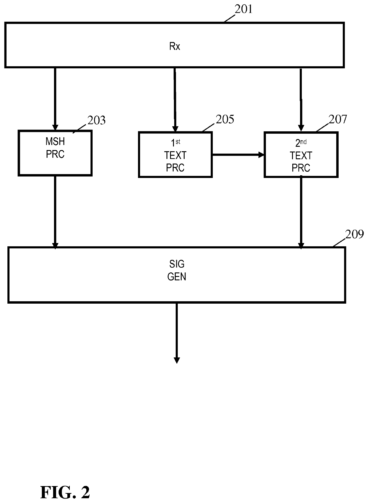
An apparatus comprises a receiver (201) for receiving an image signal comprising a number of three dimensional images representing a scene from different viewpoints, each three dimensional image comprising a mesh and a texture map, the signal further comprising a plurality of residual data texture maps for a first viewpoint being different from the different viewpoints of the number of three dimensional images, a first residual data texture map of the plurality of residual texture maps providing residual data for a texture map for the first viewpoint relative to a texture map resulting from a viewpoint shift of a first reference texture map being a texture map of a first three dimensional image of the number of three dimensional images and a second residual data texture map of the plurality of residual texture maps providing residual data for a texture map for the first viewpoint relative to a texture map resulting from a viewpoint shift of a second reference texture map being a texture map of a second three dimensional image of the number of three dimensional images. A mesh processor (203) generates a first mesh for the first viewpoint and a second mesh for the first viewpoint from an additional reference mesh being a mesh of the second three dimensional image of the plurality of three dimensional images. A first texture processor (205) generates a first intermediate texture map in response to a viewpoint transformation of the first reference texture map from a viewpoint of the first three dimensional image to the first viewpoint and an second intermediate texture map in response to a viewpoint transformation of the second reference texture map from a viewpoint of the second three dimensional image to the first viewpoint. A second texture processor (207) generates a first texture map in response to a combination of the first intermediate texture map and the first residual data texture map, and a second texture map in response to a combination of the second intermediate texture map and the second additional residual data texture map. An image generator (209) generates an image for a second viewpoint from the first texture map, the first mesh, the second texture map, and the second mesh.

Description

CROSS-REFERENCE TO PRIOR APPLICATIONS[0001]This application is the U.S. National Phase application under 35 U.S.C. § 371 of International Application No. PCT / EP2018 / 066159, filed on Jun. 19, 2018, which claims the benefit of EP Patent Application No. EP 17177649.5, filed on Jun. 23, 2017. These applications are hereby incorporated by reference herein.FIELD OF THE INVENTION[0002]The invention relates to representation of three dimensional image data / information using texture maps and meshes, and in particular, but not exclusively, to generation, encoding, and processing of an image signal comprising a number of three dimensional images each represented by a texture map and a mesh.BACKGROUND OF THE INVENTION[0003]Traditionally, technical processing and use of images has been based on two-dimensional imaging but increasingly the third dimension is being explicitly considered in image processing.[0004]For example, three dimensional (3D) displays have been developed which add a third dim...

Claims


Application Information

Patent Timeline
Patent Type & Authority Patents(United States)
IPC IPC(8): G06T15/00G06T15/20G06T15/04G06T17/20
CPCG06T15/20G06T15/04G06T17/20G06T2200/04H04N19/597H04N13/194H04N13/111H04N13/161G06T19/00H04N19/117
Inventor VAREKAMP, CHRISTIAANKROON, BARTVANDEWALLE, PATRICK LUC ELS
Owner KONINKLJIJKE PHILIPS NV
Learn More