Magnetic head for perpendicular magnetic recording having a main pole, a shield and a coil core part setback away from the medium facing surface a specified distance

a perpendicular magnetic and recording technology, applied in the direction of magnetic recording, data recording, instruments, etc., can solve the problems of increasing the length of the magnetic path through the trailing shield and the main pole, and increasing the number of steps. , to achieve the effect of reducing the length of the magnetic path

Active Publication Date: 2013-05-14
HEADWAY TECH INC +1
View PDF5 Cites 14 Cited by
  • Summary
  • Abstract
  • Description
  • Claims
  • Application Information

AI Technical Summary

Benefits of technology

[0017]It is an object of the present invention to provide a magnetic head for perpendicular magnetic recording that is capable of reducing the length of a magnetic path that passes through a main pole and a shield, the shield having an end face located in the medium facing surface at a position forward of an end face of the main pole along the direction of travel of a recording medium, and to provide a method of manufacturing such a magnetic head.
[0027]In the magnetic head for perpendicular magnetic recording and the method of manufacturing the same of the present invention, the first portion of the coil includes the first coil element and the second coil element each extending through the first space. No part of the coil other than the first and second coil elements exists in the first space. The minimum distance between the core part and the medium facing surface falls within the range of 1.4 to 4.0 μm. According to the present invention, it is therefore possible to reduce the length of the magnetic path passing through the first shield and the main pole, i.e., the length of the magnetic path passing through the first shield, the first return path section, and the main pole, wherein the first shield has an end face located in the medium facing surface at a position forward of the end face of the main pole along the direction of travel of the recording medium. The present invention also makes it possible to secure a sufficient magnetomotive force of the coil. Consequently, according to the present invention, it is possible to improve the rate of change of the direction of the magnetic flux produced from the end face of the main pole.

Problems solved by technology

The aforementioned technology, however, has the problem that the structure of the coil and the structure in the vicinity of the coil become complicated and a greater number of steps are needed to form the coil.
That is, the magnetic path through the trailing shield and the main pole is not sufficiently reduced in length.

Method used


Image

  • Magnetic head for perpendicular magnetic recording having a main pole, a shield and a coil core part setback away from the medium facing surface a specified distance
  • Magnetic head for perpendicular magnetic recording having a main pole, a shield and a coil core part setback away from the medium facing surface a specified distance
  • Magnetic head for perpendicular magnetic recording having a main pole, a shield and a coil core part setback away from the medium facing surface a specified distance

Examples


Embodiment Construction

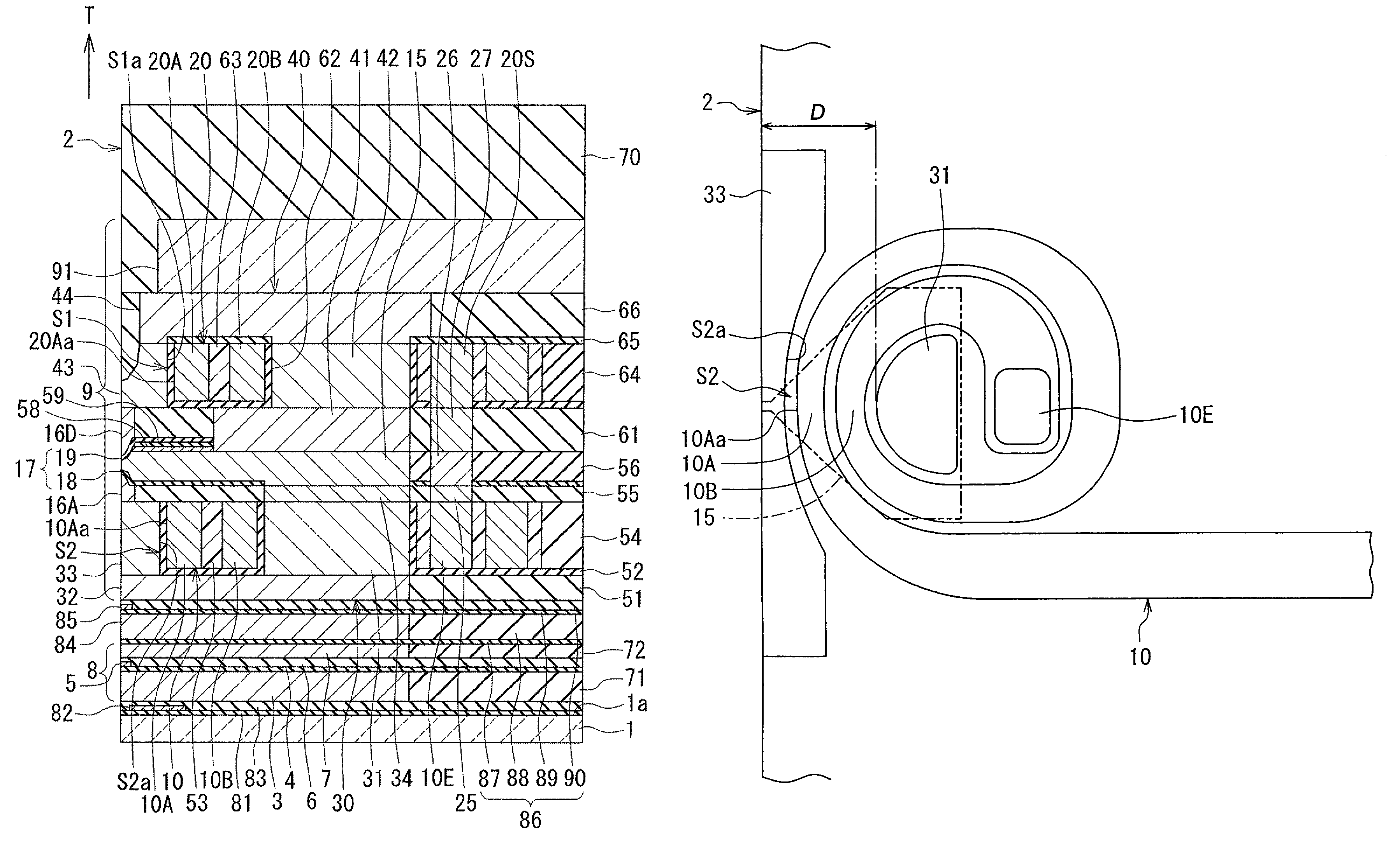
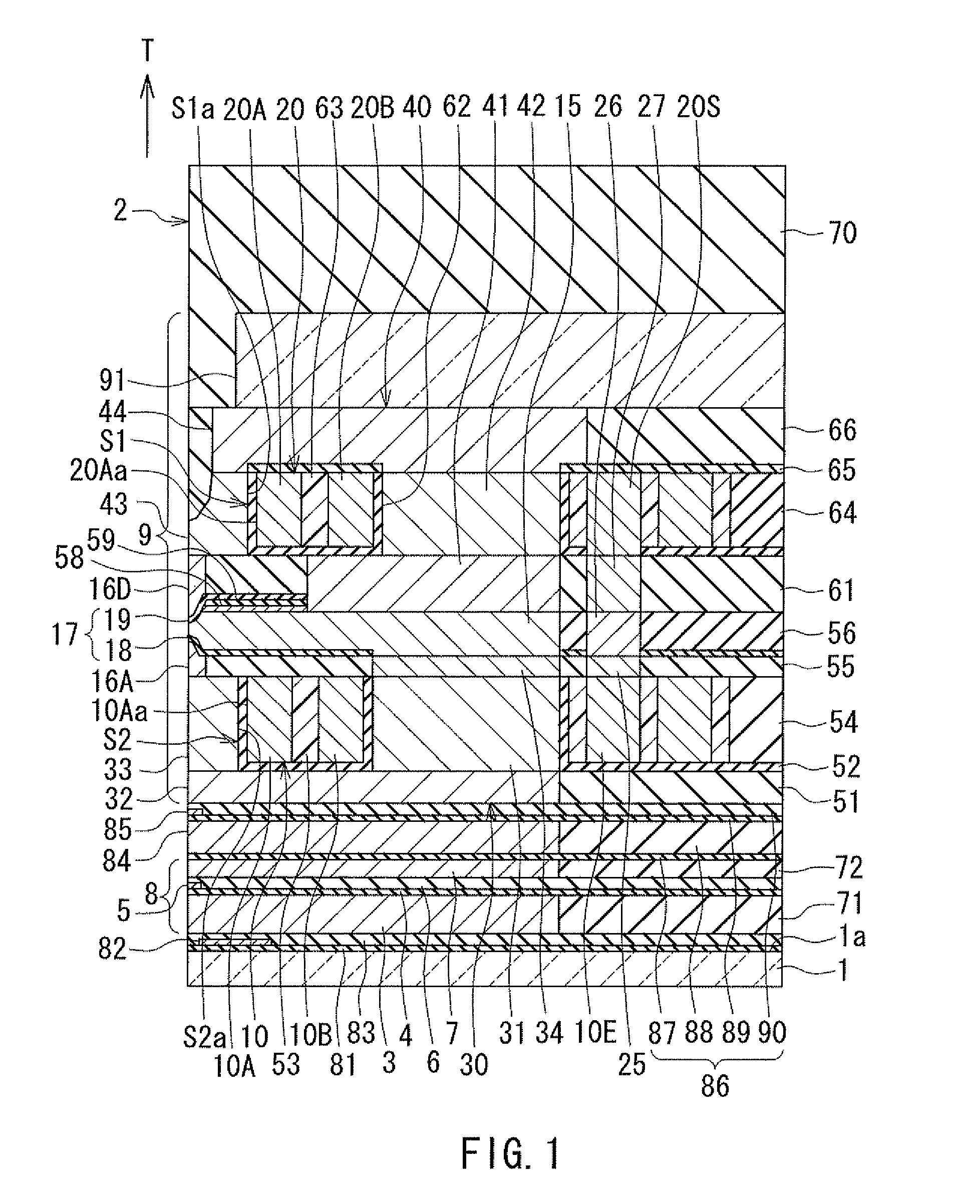
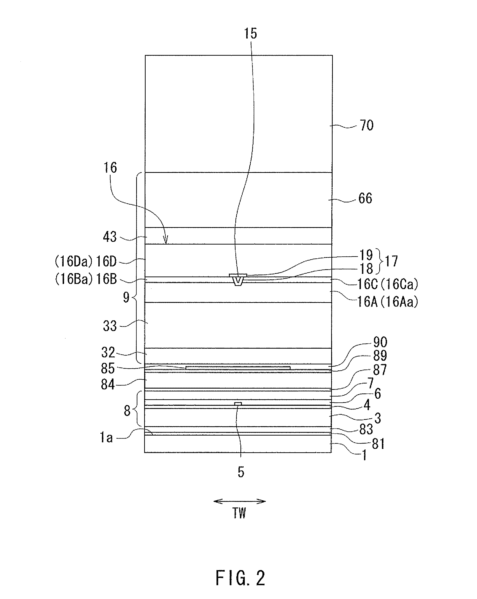
[0039]An embodiment of the present invention will now be described in detail with reference to the drawings. First, reference is made to FIG. 1 to FIG. 5 to describe the configuration of a magnetic head according to the embodiment of the invention. The magnetic head according to the embodiment is for use in perpendicular magnetic recording. FIG. 1 is a cross-sectional view showing the configuration of the magnetic head according to the embodiment. FIG. 1 shows a cross section perpendicular to the medium facing surface and the top surface of the substrate. The arrow with the symbol T in FIG. 1 indicates the direction of travel of a recording medium. FIG. 2 is a front view showing the medium facing surface of the magnetic head according to the embodiment. FIG. 3 is a plan view showing a second portion of the coil in the magnetic head according to the embodiment. FIG. 4 is a plan view showing a first portion of the coil in the magnetic head according to the embodiment. FIG. 5 is a pers...


PUM

PropertyMeasurementUnit
distanceaaaaaaaaaa
distanceaaaaaaaaaa
thicknessaaaaaaaaaa

Abstract

A magnetic head includes: a main pole; a coil; a first shield having an end face that is located in a medium facing surface at a position forward of an end face of the main pole along a direction of travel of a recording medium; and a first return path section disposed forward of the main pole along the direction of travel of the recording medium. The first return path section connects part of the main pole away from the medium facing surface to the first shield so that a first space is defined. The coil includes a first portion having a planar spiral shape and wound around a core part of the first return path section. The first portion includes first and second coil elements that each extend through the first space. No part of the coil other than the first and second coil elements exists in the first space.

Description

BACKGROUND OF THE INVENTION[0001]1. Field of the Invention[0002]The present invention relates to a magnetic head for perpendicular magnetic recording that is used for writing data on a recording medium by means of a perpendicular magnetic recording system, and more specifically, to a magnetic head for perpendicular magnetic recording that has a main pole and a shield, and a method of manufacturing the same.[0003]2. Description of Related Art[0004]The recording systems of magnetic read / write apparatuses include a longitudinal magnetic recording system wherein signals are magnetized in a direction along the plane of the recording medium (the longitudinal direction) and a perpendicular magnetic recording system wherein signals are magnetized in a direction perpendicular to the plane of the recording medium. It is known that the perpendicular magnetic recording system is harder to be affected by thermal fluctuation of the recording medium and capable of providing higher linear recording...

Claims


Application Information

Patent Timeline
Patent Type & Authority Patents(United States)
IPC IPC(8): G11B5/17
CPCG11B5/17G11B5/1278G11B5/3116G11B5/3146G11B5/315G11B5/3123Y10T29/49021
Inventor SASAKI, YOSHITAKAITO, HIROYUKISATO, KAZUKIIIJIMA, ATSUSHI
Owner HEADWAY TECH INC
Why Eureka
Try Eureka