Monitoring apparatus and system

a technology applied in the field of monitoring apparatus and system, can solve the problems of inconvenient, economic loss or even potentially hazardous situations, and the regular inspection of many such items of infrastructure in remote areas, such as irrigation sluices, gates, stock watering troughs etc., and achieve the effect of avoiding economic loss or even potentially hazardous situations, and avoiding economic loss or even prohibitive expenses

Active Publication Date: 2013-05-21
IMPRENDITORE PTY LTD
View PDF41 Cites 11 Cited by
  • Summary
  • Abstract
  • Description
  • Claims
  • Application Information

AI Technical Summary

Problems solved by technology

In many cases, particularly where such items are located in remote or difficult to reach or monitor locations, a malfunction or adverse incident may remain undetected for considerable lengths of time causing inconvenience, economic loss or even potentially hazardous situations.
Regular inspection of many such items of infrastructure in remote areas, for example irrigation sluices, gates, stock watering troughs etc is usually impractical.
Similar impracticality or prohibitive expense is associated with the monitoring for example of such items as tool sheds at building sites, tool boxes on trucks, and equipment and plant remaining on construction sites etc.
However, setting up a monitoring system is frequently a complicated procedure, often involving complex wiring of hardware installations, site visits by professional personnel.

Method used


Image

  • Monitoring apparatus and system
  • Monitoring apparatus and system
  • Monitoring apparatus and system

Examples


first preferred embodiment

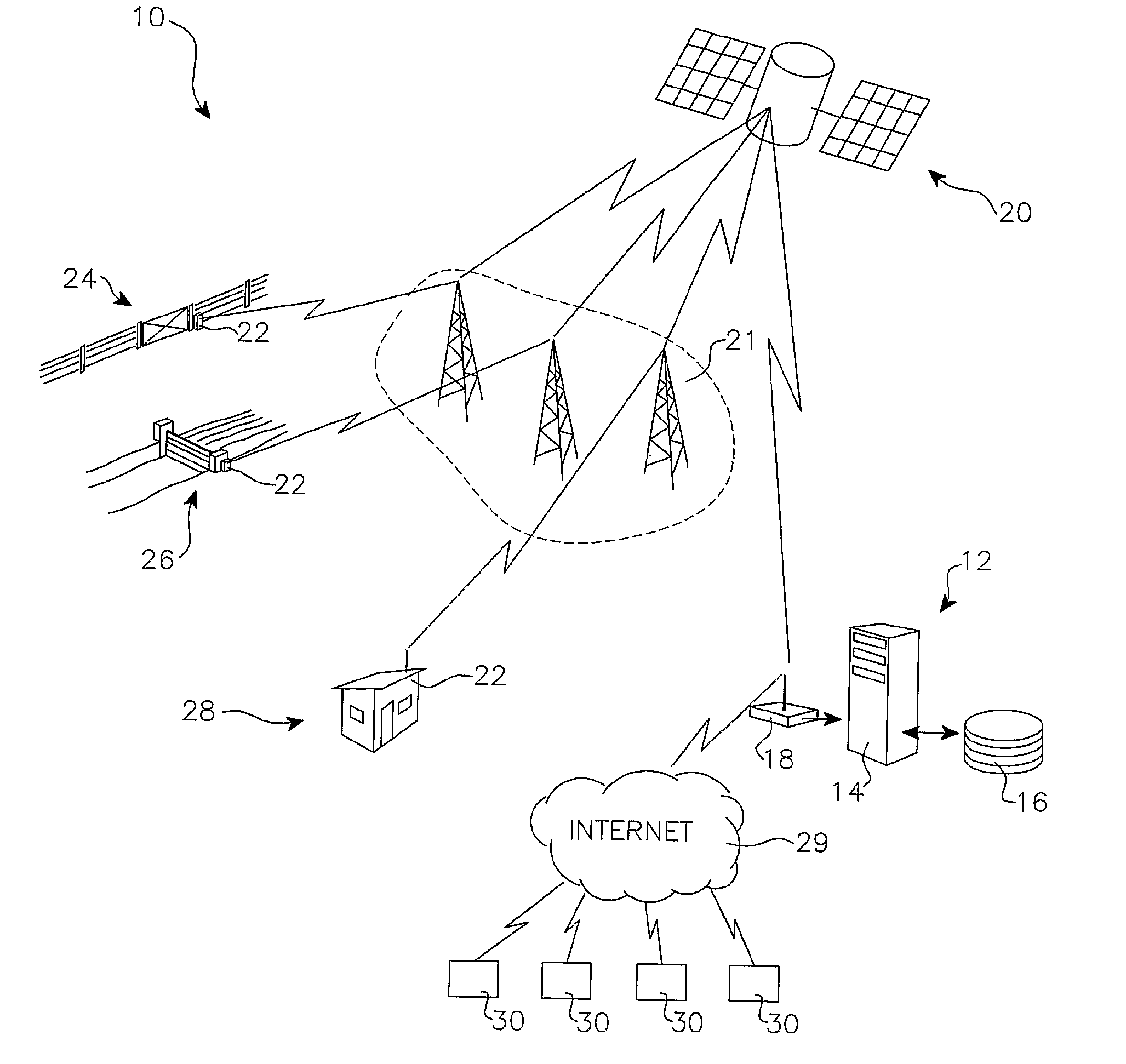
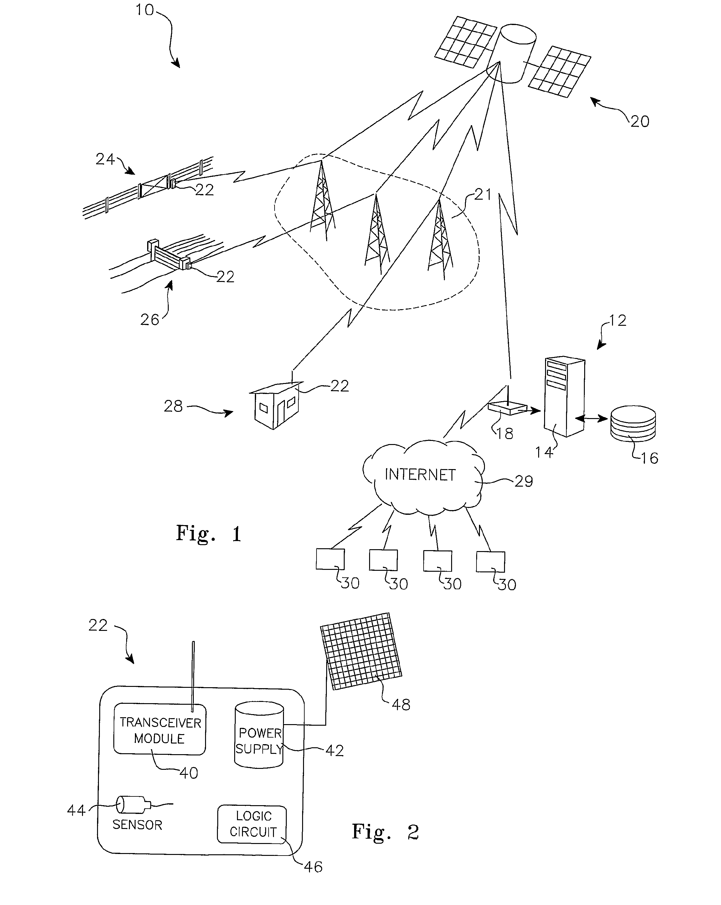
[0178]FIG. 1 is a diagrammatic representation of the apparatus and connections included in a monitoring system 10 according to a preferred embodiment of the invention. A central control facility 12 includes a data processing server 14 and data storage 16, linked to a transceiver 18. Central control facility 12 is in radio communication with a communication network such as a mobile phone network, or for example as shown in FIG. 1, with at least one communication satellite 20, by means of transceiver 18.

[0179]In the example of a communication satellite 20, it in turn, is in telecommunication contact with a number of individual signal units 22, for example via the Global System for Mobile Communications (GSM), the General Packet Radio Service (GPRS) or a similar communication network 21. Individual signal units 22 belong to registered users of the system and may be located anywhere within the signal footprint of a communication satellite (or satellites) 20, or of some other communicati...

second preferred embodiment

[0219]In a second preferred embodiment, the individual signal unit of the present invention again includes at least a transceiver module 40, a rechargeable power supply and power control module 42, and at least one external event sensor 44 and a logic circuit 46 as shown in FIG. 1. In this embodiment however, the unit may further be provided with a data storage device able to record analogue or digital input from a device connected to the individual signal unit.

[0220]In this embodiment also, the unit is not restricted in its transmission to the central control facility of it unique identifying code but is enabled to transmit the input analogue or digital data, either in real time, or retrieved from its data storage device at predetermined times or on command form the central control facility.

[0221]Thus in this form, the individual signalling unit may have attached as an input device such equipment as a video camera, sound recording equipment or a Global Positioning System (GPS) modu...


PUM


Abstract

A monitoring system for response to incidents sensed by at least one sensor of an individual signal unit; said response comprising in a first instance, transmission to a central control facility by a said individual signal unit, of at least a unique identifying code for that individual signal unit, over a communication network; said response comprising in a second instance, transmission of data from said central control facility to one or more recipients nominated by a registered owner of said individual signal unit; and wherein registration of a said individual signal unit and configuration of sensing and of said response is via a web-based interface.The monitoring system of claim 1 wherein said response in said first instance includes digital or analogue data input to said individual signal unit.In a further form there is disclosed a method of monitoring the status of an item of interest; said method including the steps of:(i) purchase by an owner of an individual signal unit and at least one user selectable sensor for connection to said device,(j) registering said individual signal unit and said at least one sensor with a central control facility,(k) configuring a response executable by said central control facility on receipt by said facility of a signal transmitted by said individual signal unit.

Description

RELATED APPLICATIONS[0001]This application is the U.S. National Phase of PCT / AU2007 / 000958 filed Jul. 12, 2007 and claims priority to Australian Provisional Patent Application No. 2006903740 filed Jul. 12, 2006 and Australian Provisional Patent Application No. 2007902358 filed May 4, 2007, which are hereby incorporated herein by reference in their entirety.[0002]The present invention relates to error and incident reporting apparatus and systems and, more particularly, to a system adapted to monitoring and acting upon status signals emanating from widely diverse and geographically separated installations.BACKGROUND[0003]The efficient functioning of modern societies relies on innumerable discrete items of infrastructure. In many cases, particularly where such items are located in remote or difficult to reach or monitor locations, a malfunction or adverse incident may remain undetected for considerable lengths of time causing inconvenience, economic loss or even potentially hazardous s...

Claims


Application Information

Patent Timeline
Patent Type & Authority Patents(United States)
IPC IPC(8): G08B1/08
CPCH04B7/1851G06F11/3089H04L67/025H04L67/12G05B15/02G06F21/6218Y04S40/18H04B10/07
Inventor RICE, PATRICK JEREMY
Owner IMPRENDITORE PTY LTD
Why Eureka
Try Eureka