Thermal barrier liner for containers

a container and thermal barrier technology, applied in the direction of rigid containers, railway components, packaging, etc., can solve the problems of undesirable or unfit consumption, traditional methods of insulating beverages, and the bottom of containers being exposed, so as to achieve the effect of effective and safe keeping beverages at the desired temperature during consumption

Inactive Publication Date: 2013-05-28
MILLERCOORS
View PDF91 Cites 36 Cited by
  • Summary
  • Abstract
  • Description
  • Claims
  • Application Information

AI Technical Summary

Benefits of technology

[0018]It is one object of the invention to provide a thermally insulated beverage container that can effectively and safely keep beverages at a desired temperature during consumption of the beverage.

Problems solved by technology

Without some means provided for insulating the container, the beverage so quickly warms that, in many circumstances, it becomes undesirable or unfit for consumption.
There are a number of disadvantages to these traditional methods of insulating beverages.
An insulating label / sleeve only covers the container sidewall, therefore leaving the bottom of the container exposed.

Method used


Image

  • Thermal barrier liner for containers
  • Thermal barrier liner for containers
  • Thermal barrier liner for containers

Examples


third embodiment

[0100]FIGS. 7 and 7A specifically illustrate this third embodiment wherein the container is under pressure and assumedly at a chilled temperature (for example below 6° C.). FIG. 8 shows the container when removed from refrigeration and warmed to a temperature wherein the solid phase change material has transitioned from a solid to liquid state. More specifically, the materials in the microcapsules 50 are shown in FIGS. 7 and 8 as transitioning from a solid state 51 to a liquid state 52.

[0101]FIGS. 9, 9A and 10 illustrate yet another preferred embodiment of the present invention. In this embodiment, the thermal barrier liner 30 comprises multiple layers 60 of a lining material wherein voids or gaps 62 exist between each of the layers. The voids or gaps between the layers may be provided in an irregular pattern. Thus, the layers do not lie evenly over one another and the layers extend non-linearly having continuous patterns of bends or curves in the liner material that form the voids ...

first embodiment

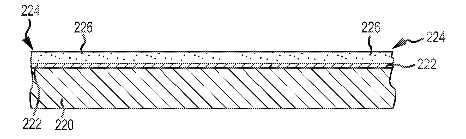
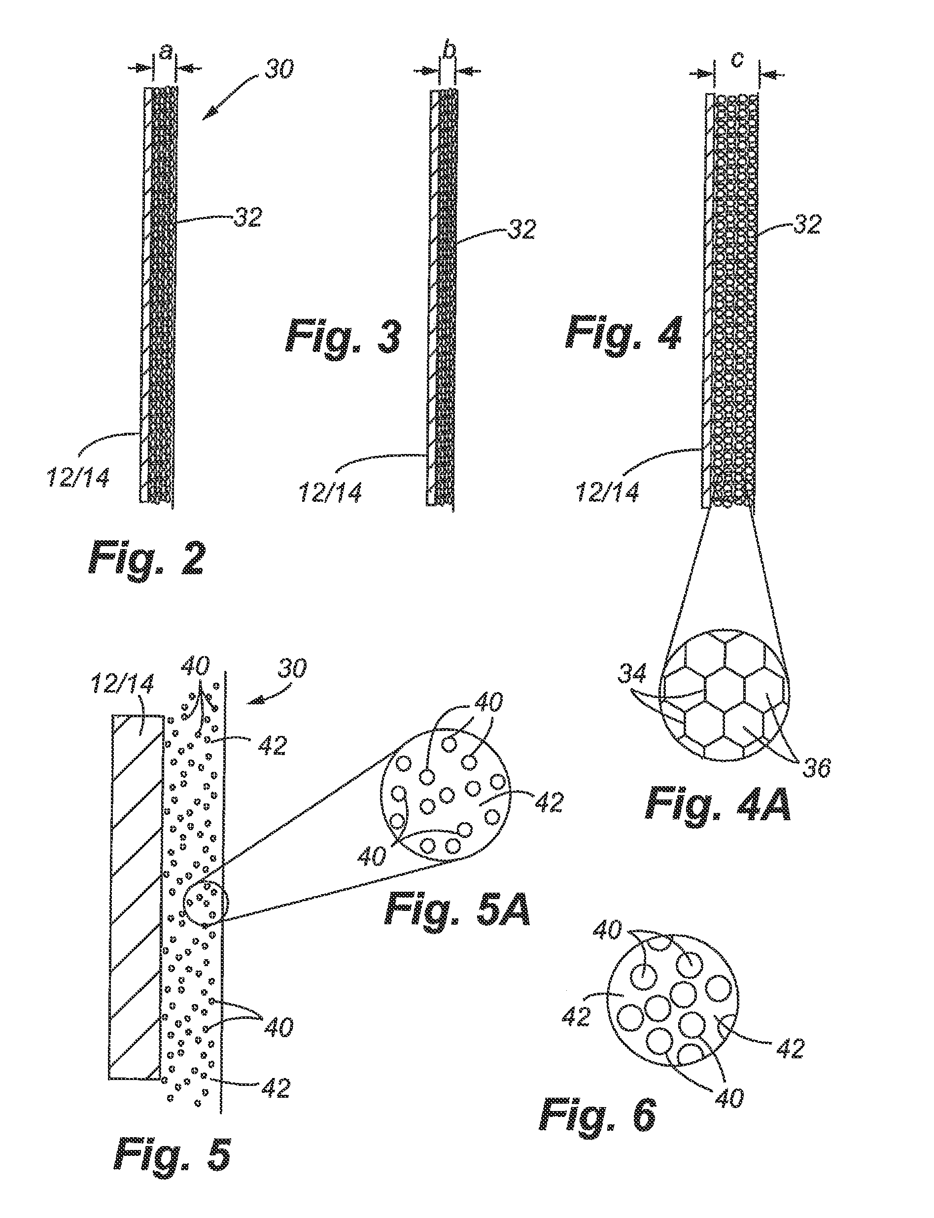
[0106]With respect to a preferred thickness of the thermal barrier liner, it shall be understood that none of the embodiments are strictly limited to a specific range but it has been found that a liner between about 1.0 mm to 3.0 mm provides adequate insulation without displacing a quantity of the beverage that adversely affects desired headspace within the container. For the first embodiment, the thermal barrier liner can be between about 0.5 mm and 1.5 mm in thickness when the container is sealed and pressurized, and the thermal barrier liner expands to between about 1.0 mm and 3.0 mm when the container is opened and exposed to the environment.

[0107]For each of the embodiments of the present invention, it shall be understood that the thermal barrier liner 30 may be used as an additional layer applied to the interior surface of the container strictly for purposes of insulation, or may also serve as a combination of a conventional interior liner of the container to prevent undesirab...

second embodiment

[0123]Referring to FIG. 17, another embodiment of the present invention is illustrated wherein a cooling element 150 is a pouch or pocket having phase change material 148 therein. More specifically, the cooling element 150 may include an upper surface 156 formed from a first sheet of flexible plastic film and a lower surface 158 made from a second sheet of flexible plastic film. The two sheets of film material are sealed to one another along an exterior edge 154 of the pouch. In FIG. 17, a substantially rectangular shaped pouch is shown. However, it shall be understood that the pouch may be configured in many different shapes to include round, or even a donut shaped pouch that frictionally engages the sidewalls of the container. In this second embodiment, the use of a flexible pouch containing the phase change material is very adaptable for placement into many different types and shapes of containers. The pouch may be shaped and sized to best accommodate the type of container that i...


PUM

PropertyMeasurementUnit
temperaturesaaaaaaaaaa
transition temperatureaaaaaaaaaa

Abstract

A thermal barrier liner maintains a beverage within a container at a desired temperature. The liner may include a closed cell substrate, a base layer having gas or liquid filled microcapsules, a base layer having microencapsulated solid-liquid phase change material, or combinations thereof. In other embodiments, an integral cooling element incorporates solid / liquid phase change material. The cooling element can either be attached to the exterior of the container, the interior of the container, or free-floating within the container. Other embodiments include container holders or direct beverage holders incorporating phase change materials to control temperature of the beverages. The embodiments may further include thermochromatic ink to provide a visible color indication of temperature changes for the beverage.

Description

CROSS REFERENCE TO RELATED APPLICATIONS[0001]This application is a continuation in part application of U.S. patent application Ser. No. 12 / 249,356, filed Oct. 10, 2008 entitled: “Thermal Barrier Liner for Containers,” now U.S. Pat. No. 8,336,729 which claims priority from the U.S. Provisional Patent Application No. 60 / 980,127 filed on Oct. 15, 2007 and entitled “THERMAL BARRIER LINER FOR CONTAINERS,” the disclosures of which are incorporated herein by reference in their entirety.[0002]This application is also a continuation in part application of U.S. patent application Ser. No. 12 / 249,431 filed Oct. 10, 2008 entitled: “CONTAINER INCORPORATING INTEGRAL COOLING ELEMENT,” now U.S. Pat. No. 8,297,072 which claims priority from the U.S. Provisional Patent Application No. 60 / 980,197 filed on Oct. 16, 2007 and entitled “CONTAINER INCORPORATING INTEGRAL COOLING ELEMENT,” the disclosures of which are also incorporated herein by reference in their entirety.FIELD OF THE INVENTION[0003]The pre...

Claims


Application Information

Patent Timeline
Patent Type & Authority Patents(United States)
IPC IPC(8): B65D1/40B65D8/04B65D81/38A47J41/00
CPCB65D17/165B65B3/00G01K11/12F25D3/08A47G19/2288B65D81/18F28D20/02G01K2207/08F25D2303/0831F25D2303/0841F25D2303/0843F25D2303/0845F25D2303/085F25D2331/805F25D2331/809F25D2331/81B65D17/4012
Inventor KELLY, JASON MORGAN
Owner MILLERCOORS
Why Eureka
Try Eureka