Inserted thermal barrier liner for containers

a technology for containers and thermal barriers, applied in the direction of decorative covers, rigid containers, packaging, etc., can solve the problems of traditional methods of insulating beverages, unfit consumption, and the bottom of containers being exposed, so as to achieve the effect of keeping beverages at the desired temperature during consumption and effective and safe us

Active Publication Date: 2012-01-17
MILLERCOORS
View PDF77 Cites 3 Cited by
  • Summary
  • Abstract
  • Description
  • Claims
  • Application Information

AI Technical Summary

Benefits of technology

[0011]It is one object of the invention to provide a thermally insulated beverage container that can effectively and safely keep beverages at a desired temperature during consumption of the beverage.

Problems solved by technology

Without some means provided for insulating the container, the beverage so quickly warms that, in many circumstances, it becomes undesirable or unfit for consumption.
There are a number of disadvantages to these traditional methods of insulating beverages.
An insulating label / sleeve only covers the container sidewall, therefore leaving the bottom of the container exposed.

Method used


Image

  • Inserted thermal barrier liner for containers
  • Inserted thermal barrier liner for containers
  • Inserted thermal barrier liner for containers

Examples


first embodiment

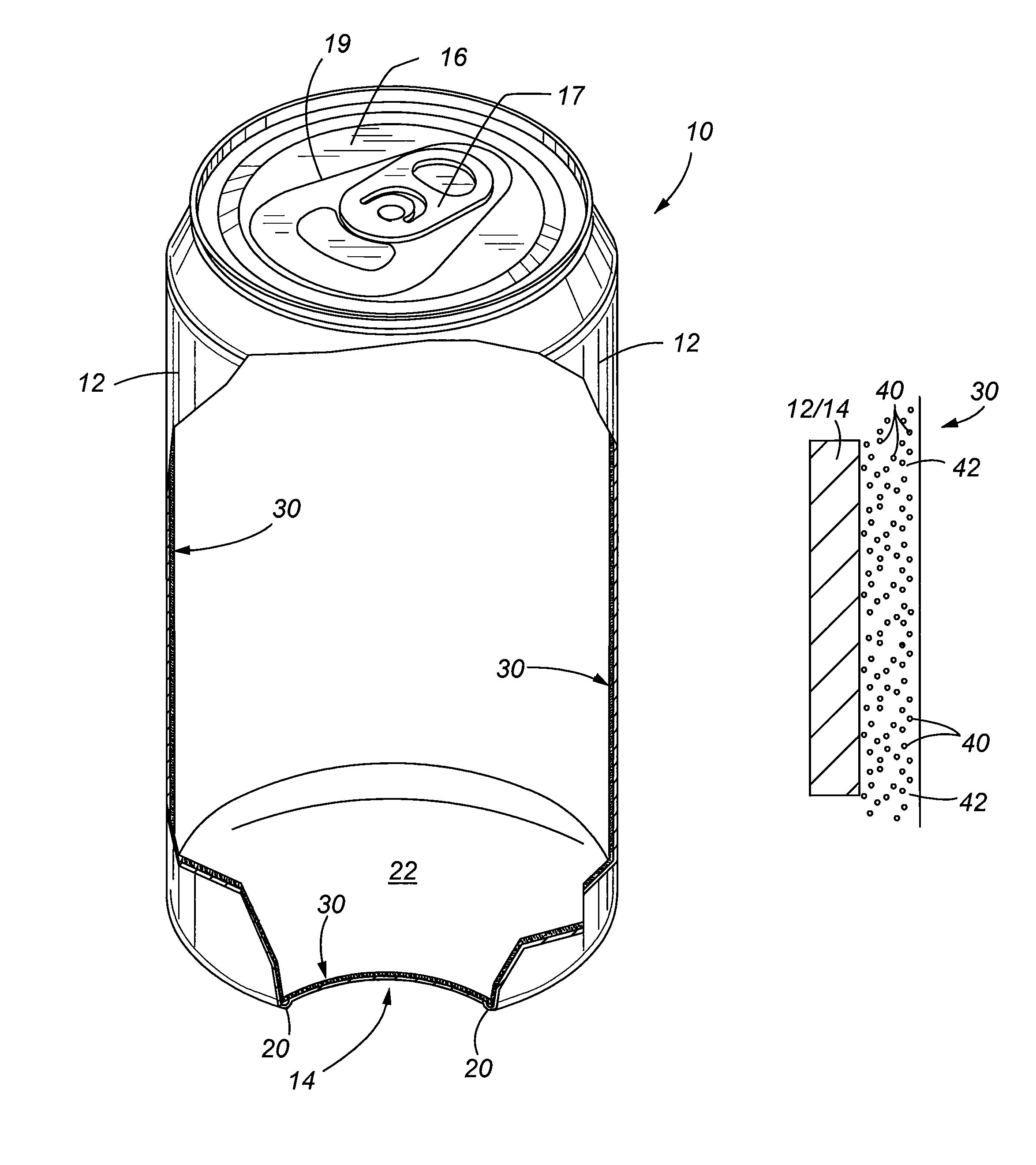
[0067]An added benefit with respect to first embodiment is that when the container is being chilled (when unopened) fast chilling of the beverage may take place since the thermal barrier liner is in its more compressed or thin state, thereby allowing rapid heat transfer away from the container without having to overcome a relatively thickened insulating member.

[0068]The permeability of the thermal barrier liner is such that gas is allowed to permeate through the cell walls over a period when under pressure to reach equilibrium, for example, a few hours, but the cell walls are not so permeable that immediate deflation takes place when ambient pressure is reduced. Therefore, the thermal barrier liner will maintain a full thickness for at least a period of time in which a consumer would normally consume the beverage. It is contemplated that it may take up to twenty-four hours for pressurized gas within the container when the container is sealed to permeate through the thermal barrier l...

third embodiment

[0075]FIGS. 7 and 7A specifically illustrate this third embodiment wherein the container is under pressure and assumedly at a chilled temperature (for example, below 6° C.). FIG. 8 shows the container removed from refrigeration and warmed to a temperature wherein the solid phase change material has transitioned from a solid to liquid state. More specifically, the materials in the microcapsules 50 are shown in FIGS. 7 and 8 as transitioning from a solid state 51 to a liquid state 52.

[0076]FIGS. 9, 9A and 10 illustrate yet another preferred embodiment of the present invention. In this embodiment, the thermal barrier liner 30 comprises multiple layers 60 of a lining material wherein voids or gaps 62 exist between each of the layers. The voids or gaps between the layers may be provided in an irregular pattern. As shown in FIGS. 9 and 9A, when the container is under pressure and unopened, the layers 60 form a more compressed, thinner profile. However, as shown in FIG. 10, when the contai...


PUM

PropertyMeasurementUnit
thicknessaaaaaaaaaa
thicknessaaaaaaaaaa
thicknessaaaaaaaaaa

Abstract

A thermal barrier liner is provided to maintain a beverage within a container at a desired temperature. The thermal barrier liner is installed so as to make intimate contact with the internal surface of the container. According to a method of the invention, the liner is pre-made and mechanically inserted in the container prior to securing the top of the container to the sidewall. A closed cell structure is incorporated in the thermal barrier material. The closed cell structure causes the thermal barrier material to be gas permeable such that voids in the closed cell structure equilibrate with ambient pressure conditions. The voids change size based on changes in ambient pressure conditions as compared to pressure conditions in the thermal barrier material.

Description

CROSS REFERENCE TO RELATED APPLICATIONS[0001]Priority is claimed from U.S. Provisional Patent Application No. 60 / 980,135 filed on Oct. 15, 2007, entitled “INSERTED THERMAL BARRIER LINER FOR CONTAINERS”, which is incorporated herein in its entirety by this reference.FIELD OF THE INVENTION[0002]The present invention relates to a thermal barrier liner for containers, and more particularly, to a thermal barrier liner placed in contact with the inner surface of the container and a method of installing the liner by mechanically inserting the liner in the container.BACKGROUND OF THE INVENTION[0003]Portable beverage containers are used to hold many types of beverages to include carbonated soft drinks, fruit drinks, and beer. It is well known to provide a protective internal liner for those containers made of metal such as aluminum or steel to help preserve the beverage within the container by preventing undesirable chemical reactions that would otherwise take place over time by direct conta...

Claims


Application Information

Patent Timeline
Patent Type & Authority Patents(United States)
IPC IPC(8): B23P11/00B65D81/38
CPCB65D25/16B65D81/3846B65D85/73Y10T29/49863Y10T29/4987Y10T29/49895Y10T29/49826
Inventor KELLY, JASON MORGANSMITH, HERBERT BRUCE
Owner MILLERCOORS
Why Eureka
Try Eureka