
Communication device

a communication device and communication technology, applied in the field of communication devices, can solve problems such as non-disclosure, and achieve the effect of more convenience and more convenien

Inactive Publication Date: 2013-05-28
CORYDORAS TECH
View PDF551 Cites 55 Cited by
  • Summary
  • Abstract
  • Description
  • Claims
  • Application Information

AI Technical Summary

Benefits of technology

The patent aims to provide mobility, convenience, and improved access for users of communication devices. It seeks to enhance the user experience when using the device in situations where they are not tethered to a fixed location. This applies to both users of the device and any other objects that the device is attached to.

Problems solved by technology

In the alternative, it may be used to compute a distance between the cellular radiotelephone and a location where the quality level of the cellular radiotelephone communication signal is predicted to be less than the predetermined value, and to determine from the computed distance whether the cellular radiotelephone should be handed off.” However, this prior art does not disclose the system comprising a communication device and an another device, (a) wherein when the communication device is identified to be located in a 1st geographic area, a pin-point location of the communication device is notified to the another device, (b) wherein when the communication device is identified to be located in a 2nd geographic area, a specific zone in which the communication device is located is notified to the another device, (c) wherein when the communication device is identified to be located in a 3rd geographic area, a false location is notified to the another device, (d) wherein when the communication device is identified to be located in a 4th geographic area, a current geographic location unknown notice is sent to the another device, and (e) wherein when the communication device is identified to be located in a 5th geographic area, a previous location which indicates the location of the communication device at a certain previous time is notified to the another device.

Method used


Image

  • Communication device
  • Communication device

Examples


Embodiment Construction

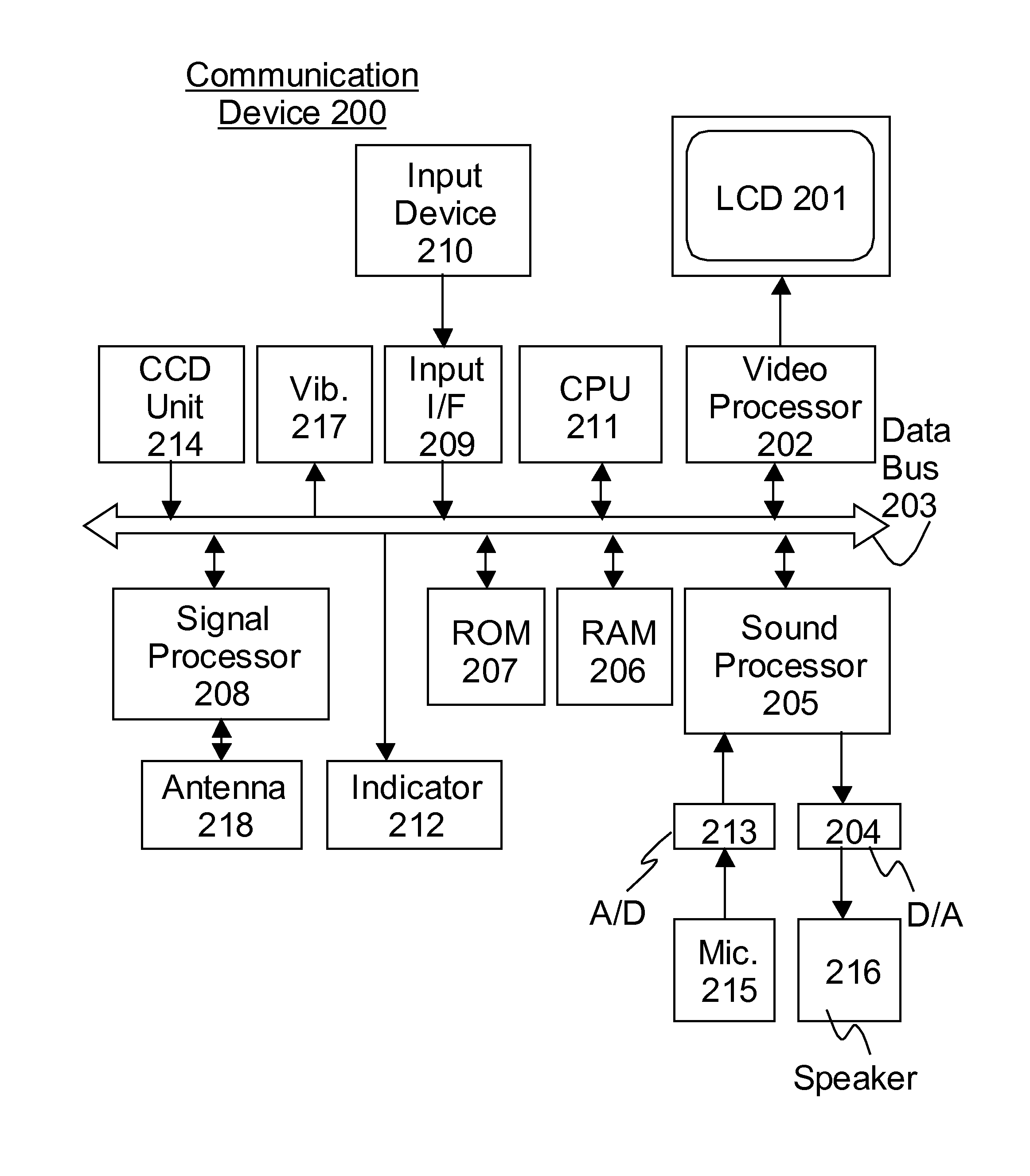
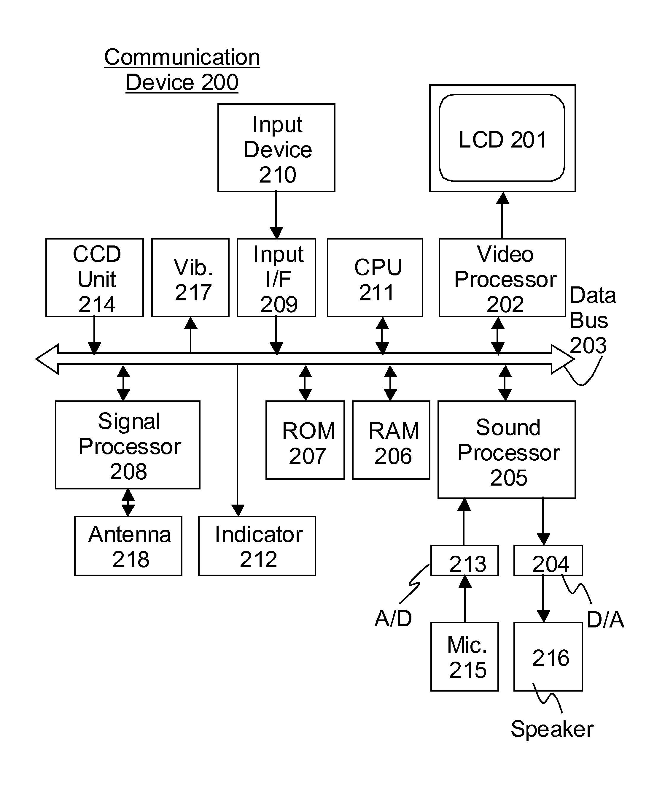
[0014]The following description is of the best presently contemplated mode of carrying out the present invention. This description is not to be taken in a limiting sense but is made merely for the purpose of describing the general principles of the invention. For example, each description of random access memory in this specification illustrate(s) only one function or mode in order to avoid complexity in its explanation, however, such description does not mean that only one function or mode can be implemented at a time. In other words, more than one function or mode can be implemented simultaneously by way of utilizing the same random access memory. In addition, the figure number is cited after the elements in parenthesis in a manner for example ‘RAM 206 (FIG. 1)’. It is done so merely to assist the readers to have a better understanding of this specification, and must not be used to limit the scope of the claims in any manner since the figure numbers cited are not exclusive. There ...


PUM


Abstract

The system comprising a communication device and an another device, (a) wherein when the communication device is identified to be located in a 1st geographic area, a pin-point location of the communication device is notified to the another device, (b) wherein when the communication device is identified to be located in a 2nd geographic area, a specific zone in which the communication device is located is notified to the another device, (c) wherein when the communication device is identified to be located in a 3rd geographic area, a false location is notified to the another device, (d) wherein when the communication device is identified to be located in a 4th geographic area, a current geographic location unknown notice is sent to the another device, and (e) wherein when the communication device is identified to be located in a 5th geographic area, a previous location which indicates the location of the communication device at a certain previous time is notified to the another device.

Description

CROSS REFERENCE TO RELATED APPLICATIONS[0001]This application is a continuation of U.S. Ser. No. 12 / 166,478, filed Jul. 2, 2008 now abandoned which is hereby incorporated herein by reference in its entirety.BACKGROUND OF INVENTION[0002]The invention relates to communication device and more particularly to the communication device which is capable to communicate with another communication device in a wireless fashion.[0003]U.S. Pat. No. 6,327,471 is introduced as prior art of the present invention of which the summary is the following: “A method and an apparatus is provided for acquiring satellite signals to establish the exact spatial position of a cellular radiotelephone, in order to perform a timely dropoff or smooth handoff to another base station or frequency. The cellular radiotelephone is equipped with its own positioning system which uses satellite data to determine its spatial position. The communication system is preferably a Code Division Multiple Access (CDMA) system, and...

Claims


Application Information

Patent Timeline
Patent Type & Authority Patents(United States)
IPC IPC(8): H04W24/00H04W4/021H04W4/029
CPCH04W64/006H04W4/021H04W4/029H04W4/023H04W4/025H04L67/52H04W68/00H04M3/42
Inventor FUJISAKI, IWAO
Owner CORYDORAS TECH
Learn More