Lubrication system with prolonged loss of lubricant operation

a technology of lubrication system and lubricant, which is applied in the direction of machines/engines, mechanical equipment, transportation and packaging, etc., can solve the problems of significant increase in conditions, complexity, design envelope, etc., and achieve the effect of facilitating the operation of the power transmission system

Active Publication Date: 2013-06-11
SIKORSKY AIRCRAFT CORP
View PDF36 Cites 14 Cited by
  • Summary
  • Abstract
  • Description
  • Claims
  • Application Information

AI Technical Summary

Benefits of technology

[0009]Should a loss of lubricant condition occur, for instance ballistic damage to the housing, the controller will recognize a pressure drop and close a breather valve to seal the housing. The controller will also open a heat exchanger valve system such that the external lubrication communication system will release lubricating oil from the hot oil sump until the intake line within the hot oil sump becomes open to air within the housing. From this point forward, the external pump system pumps air out of the housing and develop negative pressure therein. The negative pressure essentially operates as an air lock to minimize or prevent lubricating oil loss from the housing while the internal lubrication system continues to distribute lubricating oil—which although now increasing in temperature over operational time—still operates to lubricate gearbox components and maintain operation.
[0010]For further ballistic tolerance, the housing is a compound housing that includes an inner housing and an outer housing which defines a gap filled with a thick resilient material. The resilient material will flow into a penetration of the housing to reduce or close the penetration and further minimize lubricating oil and negative pressure loss.
[0013]The present invention therefore provides a lubrication system which facilitates operation of a power transmission system for a prolonged time period under oil-out conditions.

Problems solved by technology

Rotary-wing aircraft power transmission systems incorporate a multitude of gears and bearings which are subject to heat, sliding and surface wear.
Such conditions are significantly increased during loss of lubricant (LOL) operating conditions caused by, for example, ballistic damage, pump failure and system leaks.
Even through relatively effective, these existing systems may result in additional weight, complexity, and design envelope, yet still not completely satisfy certain LOL requirements.

Method used


Image

  • Lubrication system with prolonged loss of lubricant operation
  • Lubrication system with prolonged loss of lubricant operation
  • Lubrication system with prolonged loss of lubricant operation

Examples


Embodiment Construction

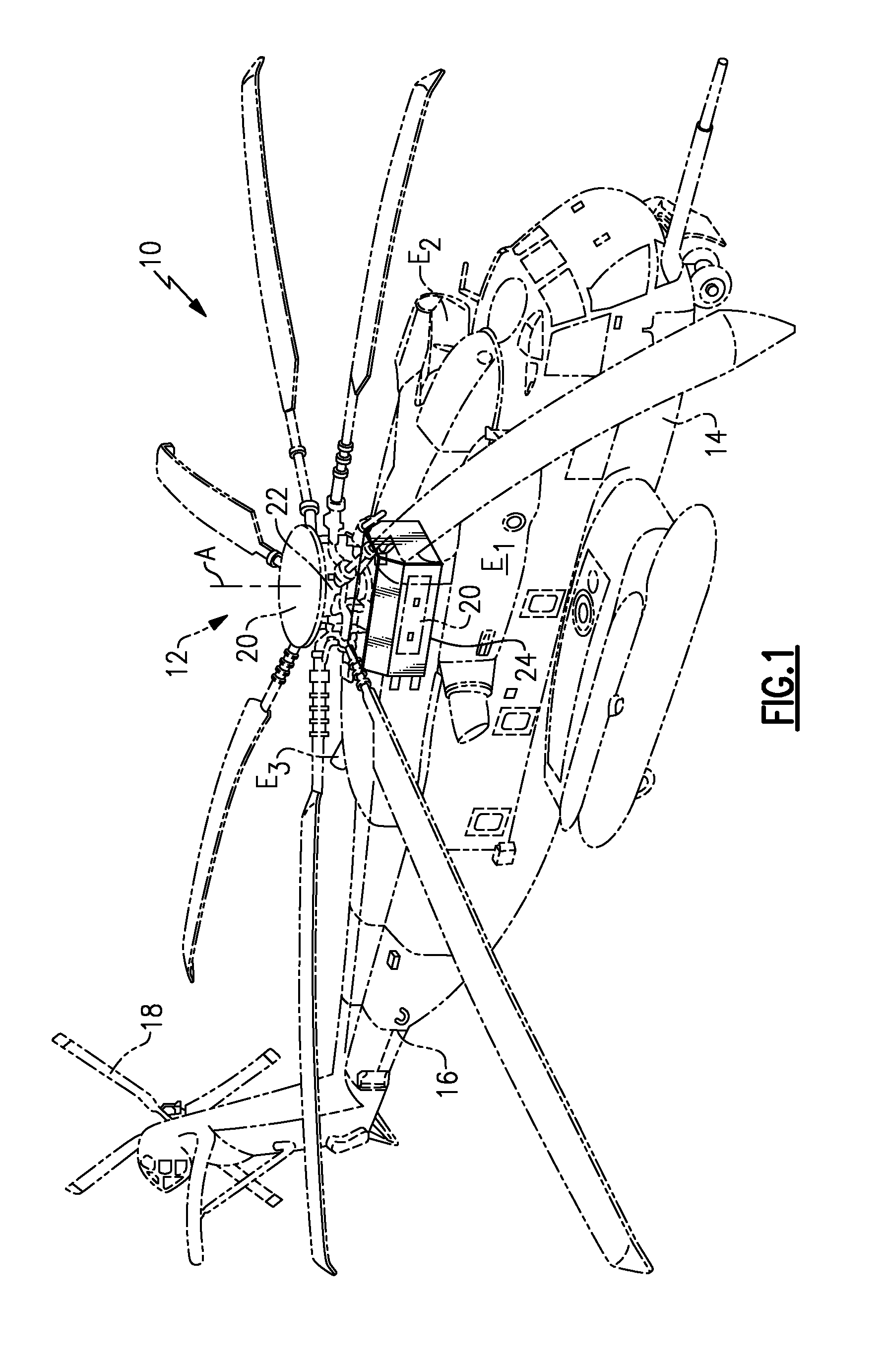
[0019]FIG. 1 schematically illustrates a rotary-wing aircraft 10 having a main rotor system 12. The aircraft 10 includes an airframe 14 having an extending tail 16 which mounts a tail rotor system 18, such as an anti-torque system. The main rotor assembly 12 is driven through a main power transmission gearbox (illustrated schematically at 20) by one or more engines E. Although a particular helicopter configuration is illustrated and described in the disclosed embodiment, other configurations and / or machines, such as ground vehicles, jet aircraft, turbofan engines, high speed compound rotary wing aircraft with supplemental translational thrust systems, dual contra-rotating, coaxial rotor system aircraft, turbo-props, tilt-rotors and tilt-wing aircraft, and such like will also benefit from the present invention.

[0020]The main power transmission gearbox 20 carries torque from the engines E through a multitude of gear train paths to a main rotor shaft 22 of the main rotor system 12. The...


PUM


Abstract

A lubrication system includes an external pump system which pumps air out of the housing and develop negative pressure therein in response to a loss of lubrication condition. The negative pressure operates as an air lock to minimize or prevent lubricating oil loss from the housing while an internal lubrication system continues to distribute lubricating oil—which although now increasing in temperature—still operates to lubricate the gearbox components. For further ballistic tolerance, the housing is a compound housing that reduces or closes the penetration and further minimizes lubricating oil and negative pressure loss. The housing may be still further hardened by an armor layer.

Description

[0001]This invention was made with government support under Contract No.: N00019-06-C-0081 awarded by the Department of the Navy. The government therefore has certain rights in this invention.BACKGROUND OF THE INVENTION[0002]The present invention relates to a lubrication system, and more particularly to a rotary-wing aircraft power transmission system having a lubrication system which provides prolonged loss of lubricant (LOL) operation.[0003]Rotary-wing aircraft power transmission systems incorporate a multitude of gears and bearings which are subject to heat, sliding and surface wear. Such conditions are significantly increased during loss of lubricant (LOL) operating conditions caused by, for example, ballistic damage, pump failure and system leaks. The primary components of a power transmission system which may be failure points under LOL conditions include bearings and gears which are constantly oil lubricated under normal conditions using pressurized oil jets or splash oil lub...

Claims


Application Information

Patent Timeline
Patent Type & Authority Patents(United States)
IPC IPC(8): F01M1/20
CPCB64C27/12F01M5/00F01M5/002F01M11/10F01M13/0011F01M2011/0045F16N17/00F16N39/02F16N2210/08
Inventor GMIRYA, YURIYGELFAND, MIKHAIL
Owner SIKORSKY AIRCRAFT CORP
Why Eureka
Try Eureka