Roof wall coping system and method

a coping system and roof wall technology, applied in the field of coping systems, can solve the problems of unsightly corrosion, roof failures, interior of buildings, etc., and achieve the effect of avoiding longitudinal shifting of a splice plate, reducing the number of components, and facilitating installation

Inactive Publication Date: 2007-01-30
VIRIDIAN SYST
View PDF13 Cites 11 Cited by
  • Summary
  • Abstract
  • Description
  • Claims
  • Application Information

AI Technical Summary

Benefits of technology

[0006]The present invention provides a coping system that has few components, is easily installed, and leaves no exposed fasteners to provide a path for moisture transfer or unsightly corrosion. Moreover, this coping system minimizes or prevents longitudinal shifting of a splice plate under the coping cap to minimize or prevent water from penetrating the system through gaps between adjacent sections of the coping cap.
[0007]More particularly, the present invention provides a system that includes a cleat mountable to a roof wall, a coping cap mountable to the cleat, a spring element extendable between the coping cap and the cleat, and a splice plate mountable to the cleat under the coping cap. The cleat includes catches and distal ends of the coping cap have inwardly turned hooks that are adapted to receive the catches, whereby when the coping cap is mounted to the cleat the spring biases the hooks into engagement with the catches. The cleat and the splice plate further include cooperating elements that minimize movement of the splice plate relative to the cleat in at least one direction.
[0009]The present invention also contemplates the combination of a cleat and a splice plate mountable on the cleat. The cleat has a width dimension that extends across a wall when mounted on a wall, and a length dimension transverse to the width dimension. When the cleat and the splice plate are mounted on a wall the cooperating elements minimize movement of the splice plate in a direction parallel to the length dimension.
[0012]The present invention also provides a method of mounting a coping system on a roof wall. An exemplary method includes the following steps: mounting at least one cleat to a roof wall, and mounting at least one splice plate to the cleat. The step of mounting the splice plate to the cleat includes moving the splice plate onto the cleat such that cooperating elements on the cleat and the splice plate move into engagement and thereby minimize movement of the splice plate relative to the cleat in a direction along the wall.

Problems solved by technology

The majority of roofing failures occur in two areas, at the edge of the roof at an exterior parapet wall and along interior walls that extend above the surface of the roof.
If the top of the walls are not protected, water can penetrate the roof system and the interior of the building and cause damage.
These fasteners can promote unsightly corrosion and also can provide a pathway for water to pass through the coping system to the building.
The sealants must be applied carefully, are messy and time-consuming to use, and can fail over time and thus require periodic maintenance.
Unfortunately, as temperature changes cause the cover to expand and contract, the drain plates can migrate away from the seams they are meant to protect.

Method used


Image

  • Roof wall coping system and method
  • Roof wall coping system and method
  • Roof wall coping system and method

Examples


Embodiment Construction

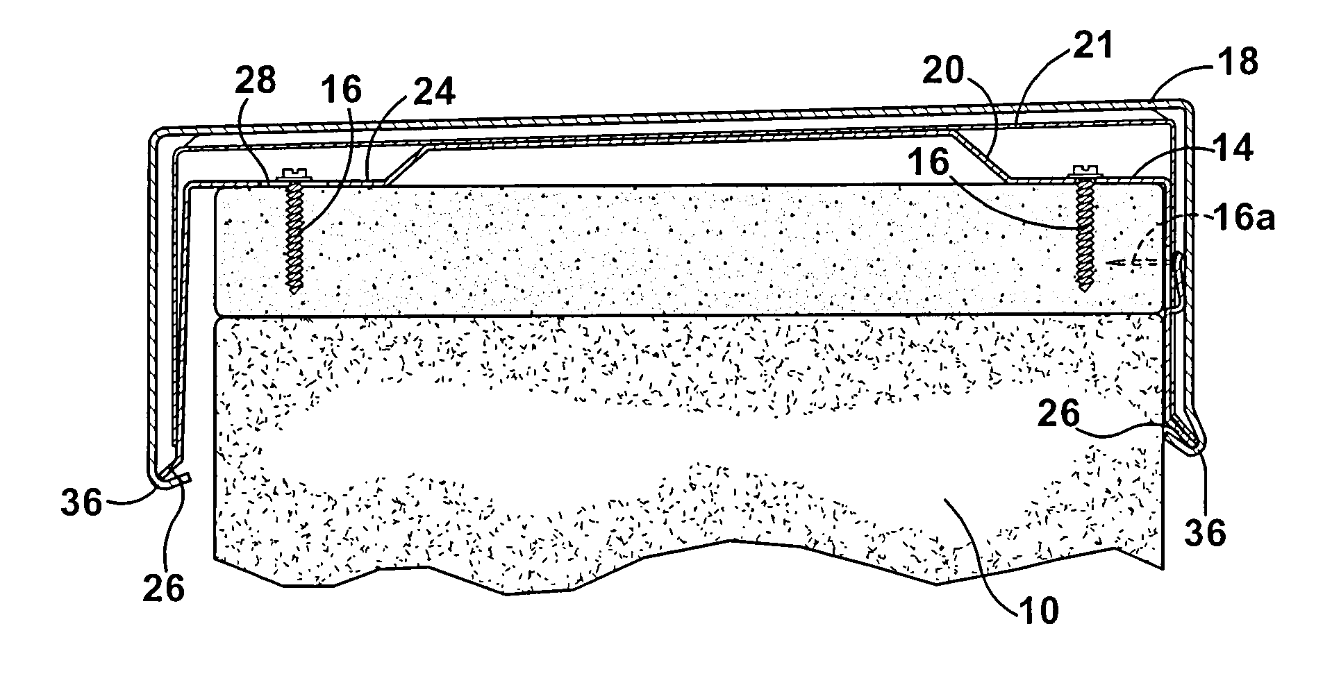
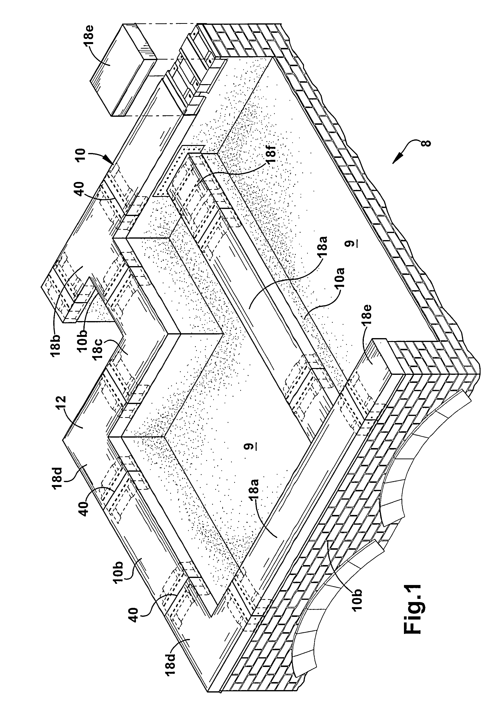
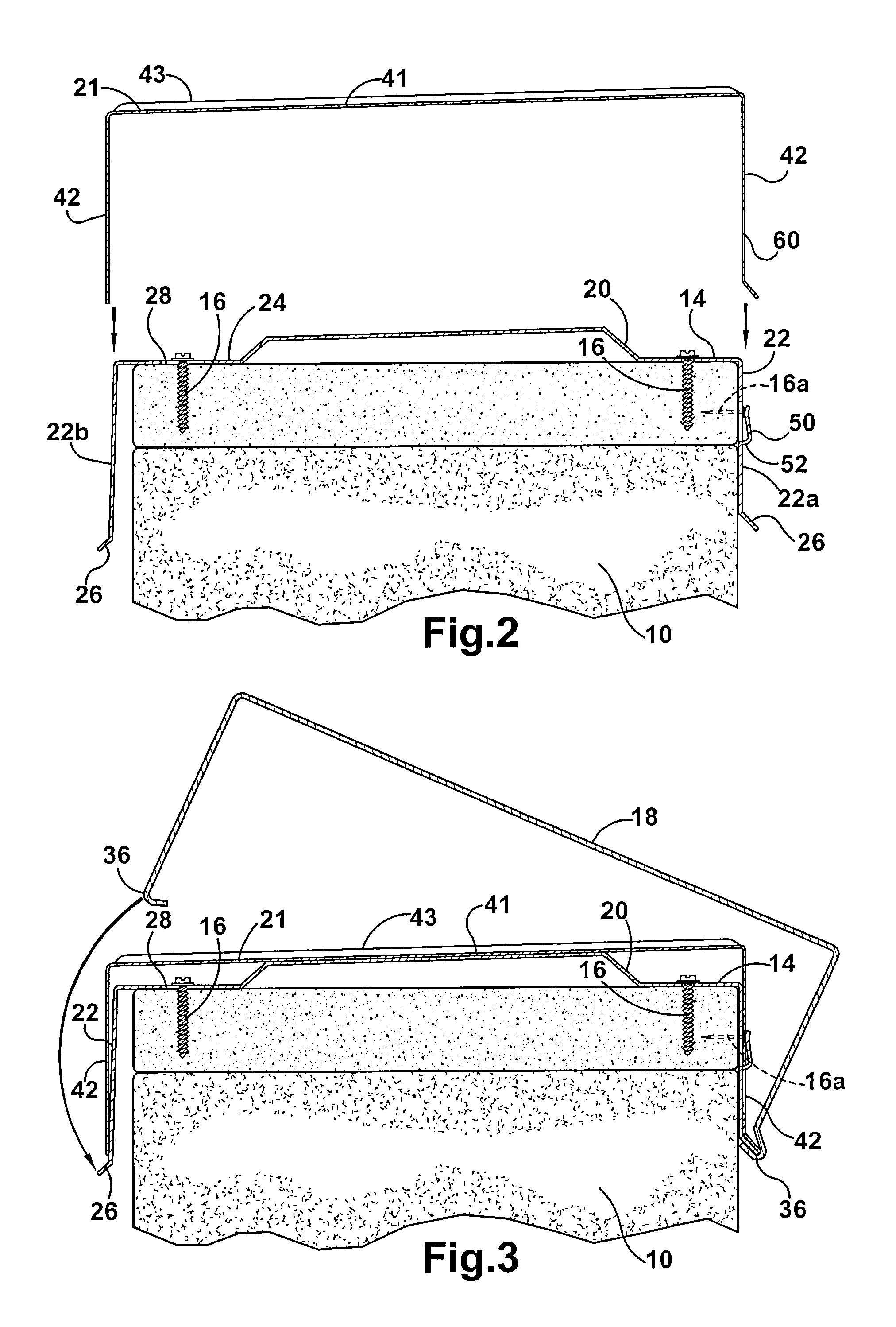
[0019]Referring initially to FIG. 1, a portion of a building 8 having a generally flat or low-slope roof 9 is shown. The illustrated building has both interior and exterior roof walls 10 protruding above the surface of the roof. The interior walls 10a, sometimes referred to as divider or short walls, typically form an upper portion of an interior wall of the building and have a roof surface on both sides of the wall. The exterior walls 10b, sometimes referred to as parapet walls, bound the periphery of the roof and protect the edge of the roof and generally only have a roof surface on an interior side of the wall.

[0020]The interior and exterior walls 10a and 10b, respectively, are exposed to the elements, and the present invention provides a coping system 12 that covers and protects the top of the roof walls and directs water impinging thereon away from the wall to minimize the opportunity for water to enter the building 8 through the wall itself or via the intersection of the wall ...


PUM


Abstract

A coping system includes a cleat mountable on a wall, a splice plate mountable over the cleat and a coping cap mountable to the cleat that is held in place by a spring between the cleat and the coping cap. In general, both the cleat and the coping cap have approximately U-shape cross-sections. The ends of the coping cap turn inwardly to form hooks that catch the ends of the cleat. The spring urges the coping cap to retain the legs of the cleat in the hooks and thus hold the coping cap to the cleat and to the wall. The splice plate is held in place on the cleat by clips that extend from the cleat and through corresponding openings in the splice plate to engage portions of the splice plate adjacent the openings, thereby preventing the splice plate from moving away from the cleat.

Description

FIELD OF INVENTION[0001]The present invention relates generally to coping systems and, more particularly, to systems for coping roof walls.BACKGROUND[0002]The majority of roofing failures occur in two areas, at the edge of the roof at an exterior parapet wall and along interior walls that extend above the surface of the roof. The term “roof walls” refers to walls that extend above a roof surface, and includes both interior and exterior walls. If the top of the walls are not protected, water can penetrate the roof system and the interior of the building and cause damage. Therefore, properly protecting roof walls is essential to protecting against water damage.[0003]Coping systems are used to cap and protect walls on building rooftops and to enhance the building's overall appearance. Coping systems typically include a cap that is installed along the top of the walls. The cap improves the appearance of the walls and increases the resistance of the roof walls to wind-driven rain. To wit...

Claims


Application Information

Patent Timeline
Patent Type & Authority Patents(United States)
IPC IPC(8): E04D13/14E04G21/00E04H12/00E04D3/38E04D3/40
CPCE04D3/405
Inventor HEIDLER, JR., CHARLES W.
Owner VIRIDIAN SYST
Why Eureka
Try Eureka