
Device for stacking flat articles on edge and a postal sorting machine equipped with at least one such device

a technology for stacking devices and flat articles, which is applied in the direction of stacking articles, article delivery, pile receivers, etc., can solve the problems of not meeting the need to stack other types of flat articles in satisfactory manner, stacker devices suffer from major risks of collision between mailpieces, and automatic apparatus is not suitable for sorting, etc., to achieve high linear speed and limit collision risks

Active Publication Date: 2013-06-11
SOLYSTIC
View PDF16 Cites 3 Cited by
  • Summary
  • Abstract
  • Description
  • Claims
  • Application Information

AI Technical Summary

Benefits of technology

[0012]An object of the invention is to remedy the various drawbacks of the prior art that are presented above. A particular object of the invention is to use the same stacker device to handle articles of various types while limiting the risks of collision. A further object of the invention is to propose such a device that is suitable for maintaining the structural integrity of the articles as they are being stacked.
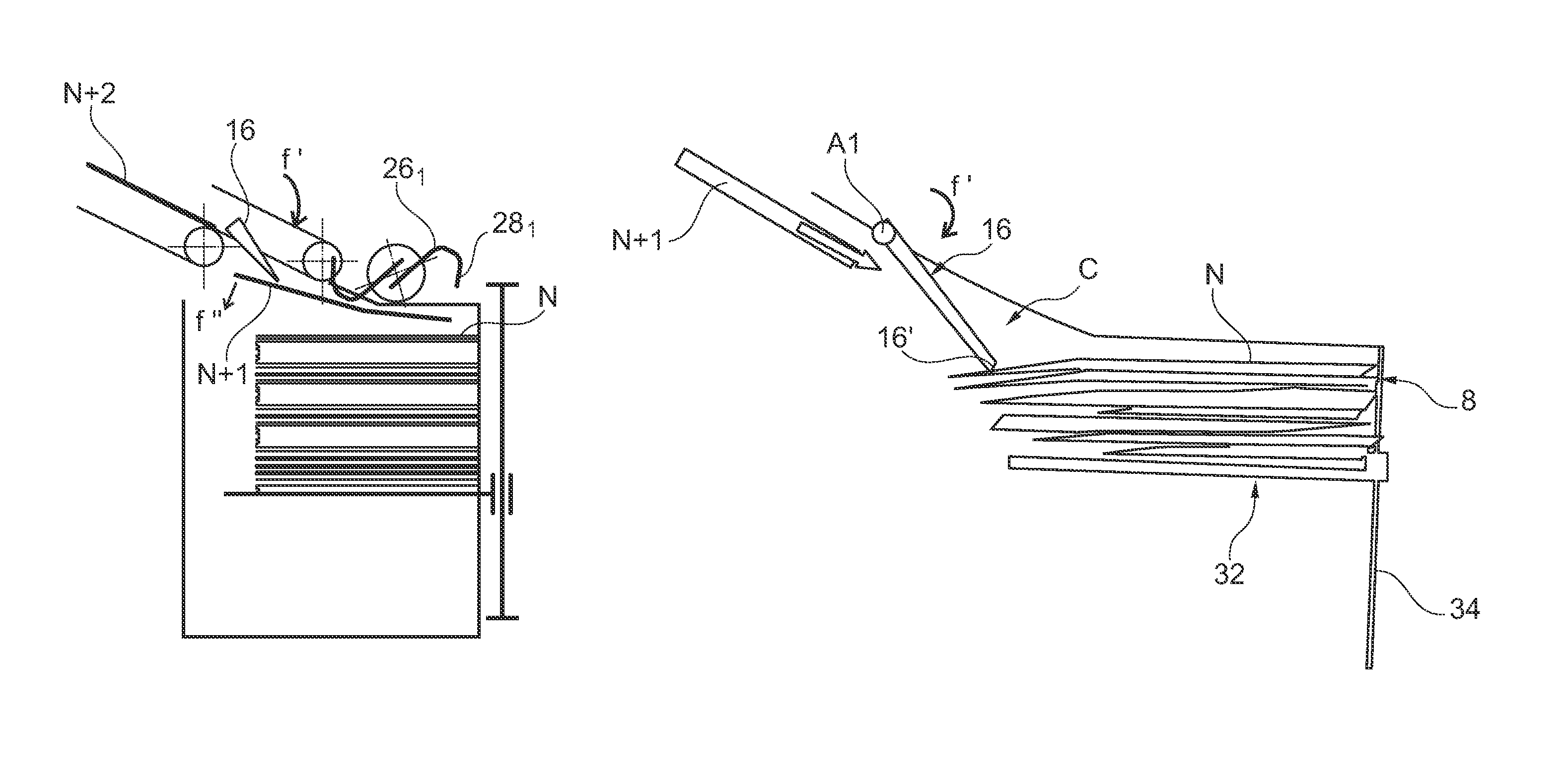
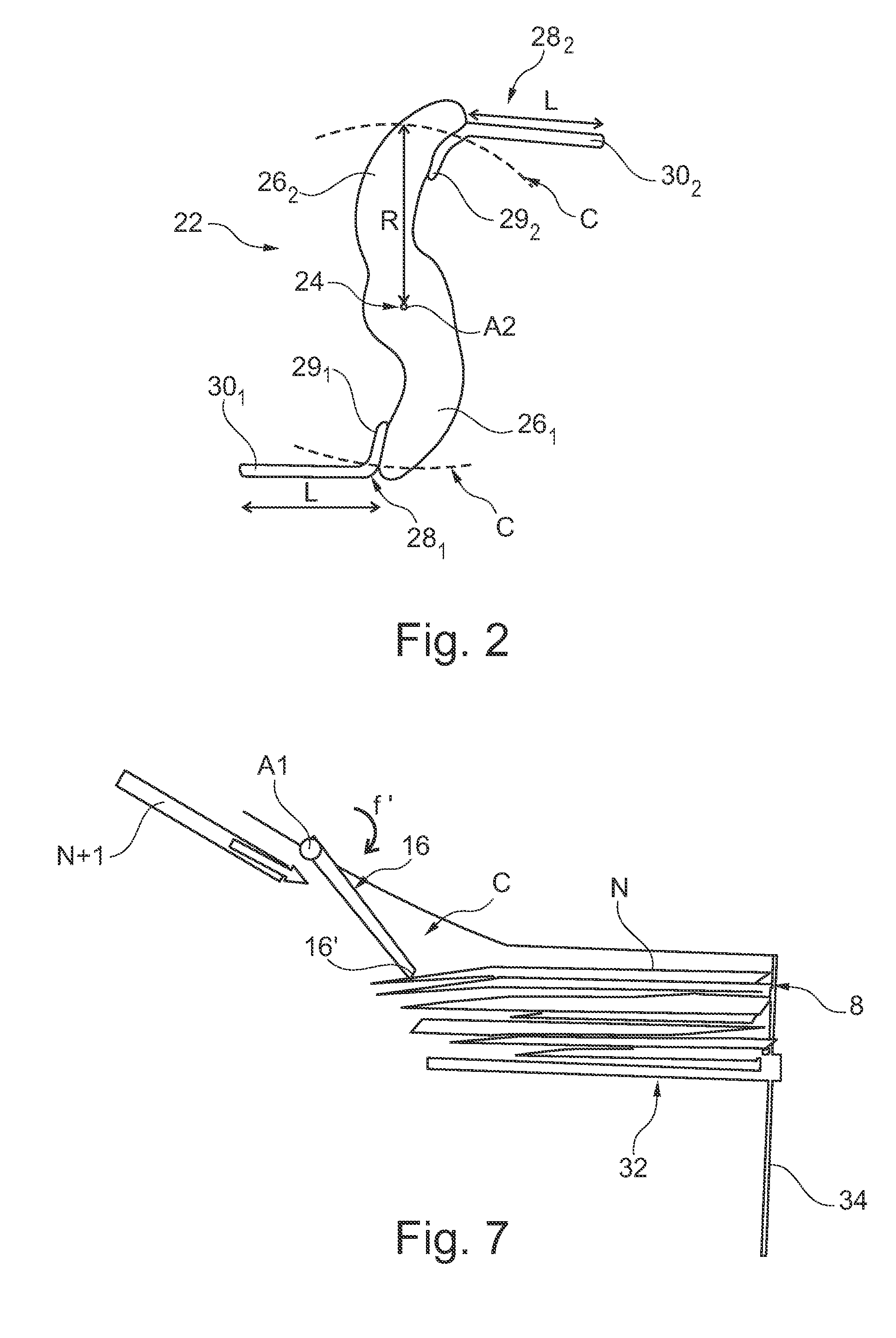
[0014]The basic idea of the invention is to interpose at least one protective member, carried by the actuator, between the leading portion of the article currently being stacked and the adjacent article that is part of the stack that is being formed. This thus makes it possible to isolate the facing surface of said adjacent article, so that it is protected from the arrival of the current article. This is particularly advantageous when the adjacent article is fragile, in view of the relatively high linear speed of the current article.
[0015]In addition, such a protective member is suitable for modifying the path of the current article. In particular, it can accompany the current article as it is arriving, so as to steer it towards the jogging edge. In other words, said protective member provides not only an interface function, but also an additional guide function. In particular, the deflector flap that is placed upstream from the actuator provided with curved spurs and that can take up a retracted position or a deployed position, and control means for controlling the deflector flap and the actuator, which control means are designed so that the deflector flap in the deployed position causes the trailing portion of a current article being stacked to tilt while the actuator accompanies the movement of the leading portion of said current article towards the jogging edge makes it possible to limit the risks of collision between the flat articles.
[0016]The stacker device of the invention may have the following advantageous characteristics:

Problems solved by technology

However, it does not meet the need to stack other types of flat article in satisfactory manner.
Banknotes are flat articles of thickness and of stiffness that are substantially constant, and that automated apparatus is not suitable for sorting mailpieces that are of various dimensions and / or that have a variety of mechanical characteristics.
Unfortunately, such stacker devices suffer from major risks of collision between mailpieces.

Method used


Image

  • Device for stacking flat articles on edge and a postal sorting machine equipped with at least one such device
  • Device for stacking flat articles on edge and a postal sorting machine equipped with at least one such device
  • Device for stacking flat articles on edge and a postal sorting machine equipped with at least one such device

Examples


Embodiment Construction

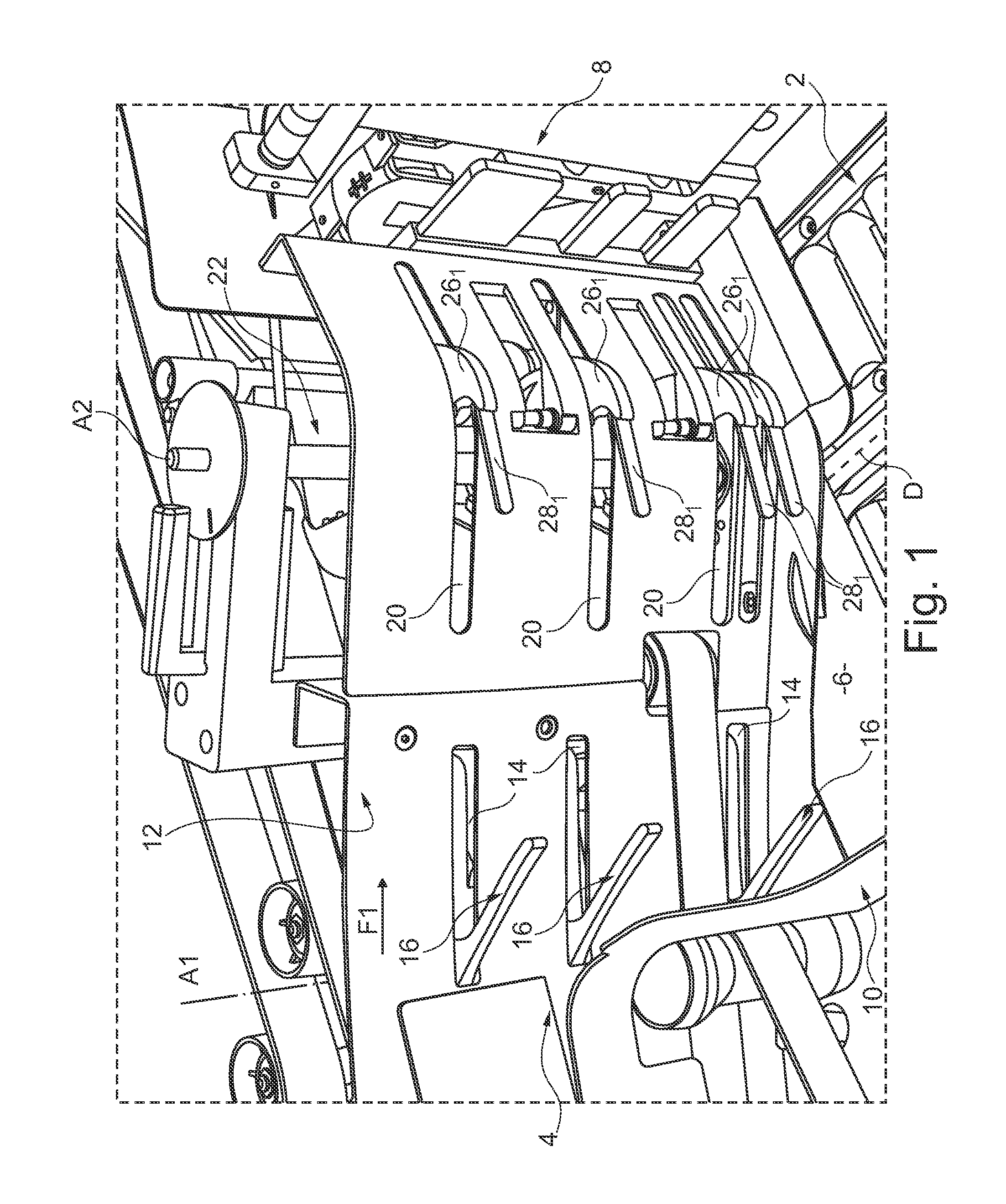
[0030]The stacker device of the invention includes firstly a stationary frame that is designated by reference 2. It also has an inlet corridor 4, through which the flat articles arrive. Typically, this inlet is put into communication with a conveyor device (not shown) that is part of a conventional-type sorting machine.

[0031]This stacker device further defines an article-receiving zone 6 for receiving the articles, which zone is flanked on one side by a jogging edge 8, against which the flat articles bear, and on the other side by a retaining edge 10. The longitudinal direction of the device is referenced D, and the stack of articles moves in said longitudinal direction as the stack is being formed. A plate 12 forming a slide edge makes it possible to guide, as indicated by the arrow F1, the flow of articles admitted from the inlet 4 towards the zone 6.

[0032]In its upstream portion, relative to the direction of advance of the articles, the plate 12 is provided with a first series of...


PUM

PropertyMeasurementUnit
lengthaaaaaaaaaa
radiusaaaaaaaaaa
axis of rotationaaaaaaaaaa

Abstract

This device has an arrival corridor via which the articles arrive, an article-receiving zone on which a stack (P) of said articles is formed, and a rotary actuator (22) suitable for pushing said articles away against a retaining element (32) for retaining the stack. The actuator (22) has at least one protective member (281, 282) for protecting the last article (N) in the stack (P) being formed, said protective member being suitable for being interposed between said last article and a current article (N+1) coming from the arrival corridor.

Description

CROSS REFERENCE TO RELATED APPLICATION(S)[0001]This application is a 35 U.S.C. §371 National Phase Entry Application from PCT / FR2011 / 051230, filed May 30, 2011, designating the United States and also claims the benefit of French Application No. 1054813, filed Jun. 17, 2010, the disclosures of which are incorporated herein by reference in their entirety.TECHNICAL FIELD[0002]The invention relates to a device for stacking flat articles on edge, and to a postal sorting machine equipped with at least one such stacker device.[0003]In the meaning of the invention, a “flat article” is, particularly but not exclusively, a mailpiece. Mailpieces that are suitable for being stacked by means of the stacker device of the invention may be of various dimensions, and may also have a variety of mechanical properties, in particular as regards stiffness. The mailpiece may, inter alia, be an ordinary letter, a magazine, an envelope with or without a window, a newspaper, or a catalogue wrapped in a plast...

Claims


Application Information

Patent Timeline
Patent Type & Authority Patents(United States)
IPC IPC(8): B65H29/44
CPCB07C3/008B65H29/40B65H29/52B65H31/06B65H2701/1916B65H2701/1313B65H2513/40B65H2511/514B65H2301/321B65H2301/4214B65H2404/1114B65H2404/63B65H2404/652B65H2404/693B65H2220/01B65H2220/02B65H2220/11
Inventor MOULIN, RAPHAELPELLEGRIN, LAURENTDE SOUSA, OLIVIERCAMPAGNOLLE, PIERRE
Owner SOLYSTIC
Learn More