Pouch transport grippers

a technology of transport grippers and pouches, applied in the field of machine tools, can solve the problems of unsightly and customer complaints, defeating the purpose of the machine, and the pouches are prone to depressing, so as to increase the weight of the pouch and increase the gripping power

Active Publication Date: 2013-06-25
MAMATA ENTERPRISES
View PDF20 Cites 9 Cited by
  • Summary
  • Abstract
  • Description
  • Claims
  • Application Information

AI Technical Summary

Benefits of technology

[0015]The inventive structure includes a pouch-gripping apparatus that does not reply upon springs for its gripping power, that does not mar the pouch even when the pouch is gripped very tightly, which does not bend the pouches into an “S” shape, and which increases the strength of its grip as the weight of the product charged into the pouch increases.
[0021]A rim of a pouch is positioned in abutting relation to the vertically disposed stop wall when the second arm is in its angled position of repose. The rim of the pouch is sandwiched between the plug and the vertically disposed stop wall when the second arms rotates until it is substantially horizontal and substantially parallel to the second arm. The plug and the vertically disposed stop wall therefore exert pressure on the rim and the pressure increases as the weight of the pouch increases as it is filled with product because such weight will pull the pouch down, thus forcing the second arm to rotate further away from its position of repose and increasing the pressure between the plug and the stop wall.
[0027]An important object of the invention is to provide a pouch-gripping mechanism that does not drop a pouch when a load is charged abruptly or gradually into the pouch.
[0030]Another important object is to provide a gripper that increases its gripping power as the weight of the pouch increases as it is being filled with product.

Problems solved by technology

The mechanical grippers of the prior art may drop the pouch if a heavy product is dropped into it because the gripping means is typically spring-loaded.
This problem has been countered by increasing the strength of the springs that provide the power behind the metallic gripping surfaces of the prior art machines, but that creates the problem of forming depressions in the pouch where the gripper engages the pouch, due to the strength of the pinch required to prevent pouch dropping.
These depressions mar the pouches, making them unsightly and the subject of customer complaints.
When such condition occurs, human operator intervention is required, thus defeating the purpose of the machine.

Method used


Image

  • Pouch transport grippers
  • Pouch transport grippers
  • Pouch transport grippers

Examples


Embodiment Construction

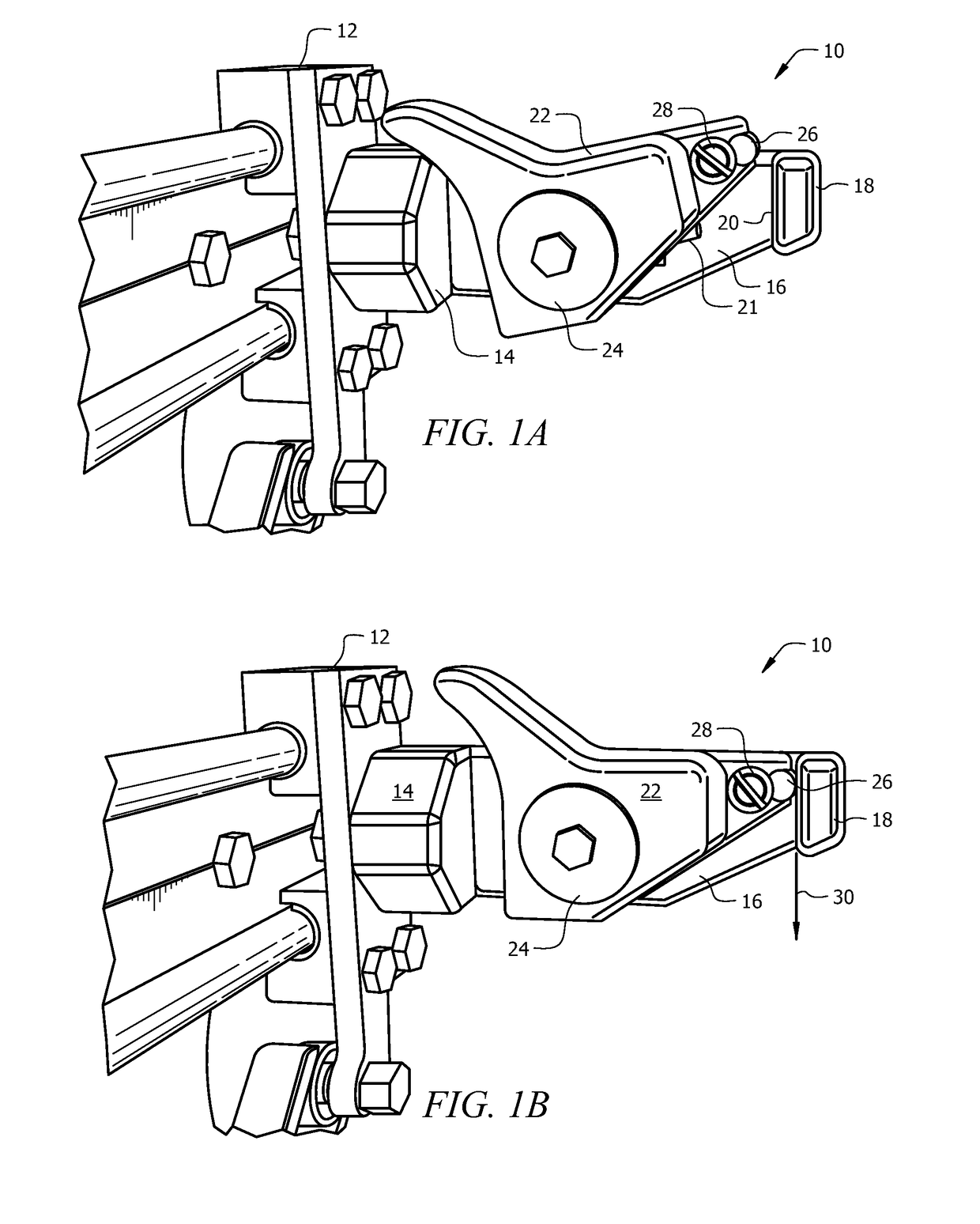
[0041]FIGS. 1A and 1B depict an illustrative embodiment of the novel gripper which is denoted as a whole by the reference numeral 10.

[0042]Gripper 10 is mounted to vertical plate 12 in this illustrative embodiment, it being understood that said vertical plate can be mounted to any suitable support surface.

[0043]Gripper 10 includes base 14 that abuts and is tightly secured to vertical plate 12.

[0044]Stationary arm 16 is formed integrally with base 14 and projects outwardly therefrom in a substantially horizontal plane in perpendicular relation to the plane of vertical plate 12. Distal free end 18 of arm 16 has an “L”-shape best seen in plan view. Stationary arm 16 is preferably formed of white FDA POM plastic.

[0045]The transversely extending part of the “L”-shaped distal free end of stationary arm 16 forms a vertical wall that faces vertical plate 12. For convenience, that vertical wall is referred to as stop wall 20.

[0046]Second arm 22 is rotatably mounted to stationary arm 16 at pi...


PUM


Abstract

A pouch-gripping apparatus includes a frame having a vertical mounting surface and a base mounted to that surface. A stationary arm projects outwardly from the vertical mounting surface. The stationary arm has an “L”-shaped distal free end that defines a stop wall. A second arm is rotatably mounted to the stationary arm and a plug is secured to the free end of the second arm. The second arm has a position of repose where it is angled relative to the stationary arm. The plug bears against the stop wall when the second arm rotates from the position of repose to a substantially horizontal position. A rim of a pouch sandwiched between the plug and the stop wall is held by the pressure between the plug and the stop wall and the pressure increases as a weight of the pouch increases.

Description

BACKGROUND OF THE INVENTION[0001]1. Field of the Invention[0002]This invention relates, generally, to machinery. More particularly, it relates to mechanical grippers that engage flexible pouches.[0003]2. Description of the Prior Art[0004]Flexible pouches are in widespread use for holding a wide variety of products. Typically, a form, fill and seal machine includes multiple mechanical pouch gripper assemblies of metallic construction. One assembly includes a pair of grippers disposed in lateral relation to one another at opposite ends of the pouch. Various means are used to open a pouch so that product may be charged into it and for closing the pouch after the product has been charged into it.[0005]The mechanical grippers of the prior art may drop the pouch if a heavy product is dropped into it because the gripping means is typically spring-loaded. The shock of impact can be sufficient to overcome the spring-loaded grip. If a heavy product is gradually charged into a pouch, the sprin...

Claims


Application Information

Patent Timeline
Patent Type & Authority Patents(United States)
IPC IPC(8): B65B43/28B65B43/26
CPCB65B43/28
Inventor UEBLER, RANDY M.FREED, FREDDO, HUYSZALKAI, TAMAS
Owner MAMATA ENTERPRISES
Why Eureka
Try Eureka