
Display apparatus

a technology of display apparatus and display screen, which is applied in the direction of electric apparatus casings/cabinets/drawers, instruments, machine supports, etc., can solve the problems of increasing the manufacturing cost of display apparatus, reducing the visibility of display screen, and increasing the cost of packing products, etc., and achieves small and simple structure

Active Publication Date: 2013-06-25
SATURN LICENSING LLC
View PDF14 Cites 4 Cited by
  • Summary
  • Abstract
  • Description
  • Claims
  • Application Information

AI Technical Summary

Benefits of technology

[0005]However, in the technique disclosed in the above listed patent publications, a relatively large stand is necessary to support a display unit arranged with a display screen. Therefore, there is an issue in that the manufacturing cost of the display apparatus increases. In addition, a visual field of a user would include the large stand arranged outside the display screen, and this causes an issue of reducing the visibility of the display screen.
[0006]Moreover, when a product or the like is shipped, it is necessary to pack not only the main body of the apparatus having the display screen arranged therein but also the stand. When the stand is large, however, the volume of the packed product increases, which causes an issue of reducing the efficiency of transport.
[0007]In view of the foregoing, it is desirable to provide a novel and improved display apparatus having a small and simple structure and capable of supporting the display unit having the display screen arranged therein.
[0013]According to the present invention, a display apparatus is provided, which has a small and simple structure and can support the display unit having the display screen arranged therein.

Problems solved by technology

Therefore, there is an issue in that the manufacturing cost of the display apparatus increases.
In addition, a visual field of a user would include the large stand arranged outside the display screen, and this causes an issue of reducing the visibility of the display screen.
When the stand is large, however, the volume of the packed product increases, which causes an issue of reducing the efficiency of transport.

Method used


Image

  • Display apparatus
  • Display apparatus
  • Display apparatus

Examples


Embodiment Construction

[0039]Hereinafter, preferred embodiments of the present invention will be described in detail with reference to the appended drawings. Note that, in this specification and the appended drawings, structural elements that have substantially the same function and structure are denoted with the same reference numerals, and repeated explanation of these structural elements is omitted.

[0040]The explanation will be made in the following order.

[0041]1. Entire structure of display apparatus

[0042]2. Details of support structure

[0043]3. Exemplary configuration of tilt mechanism

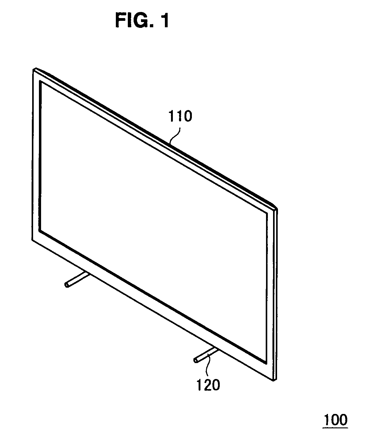
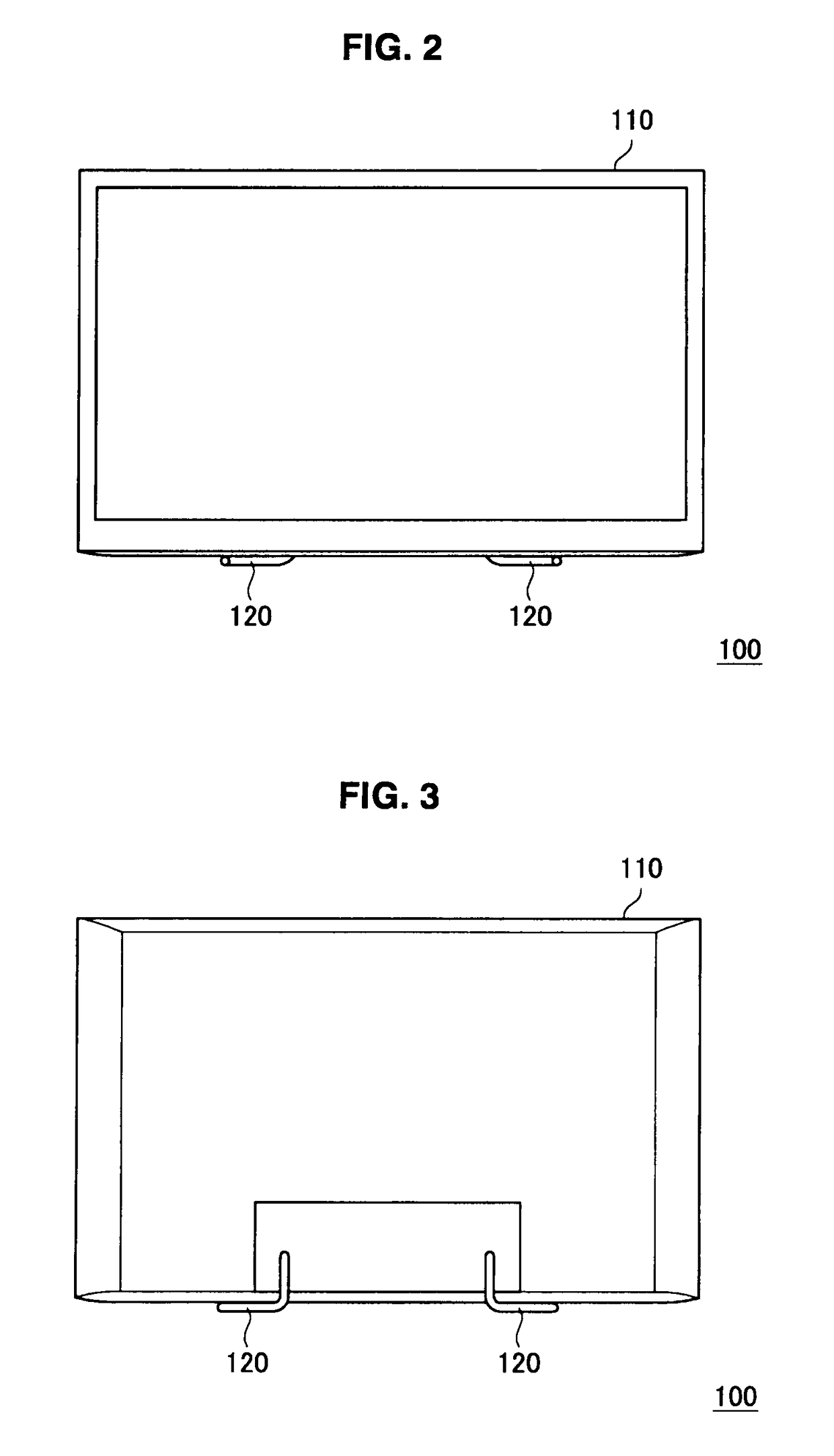
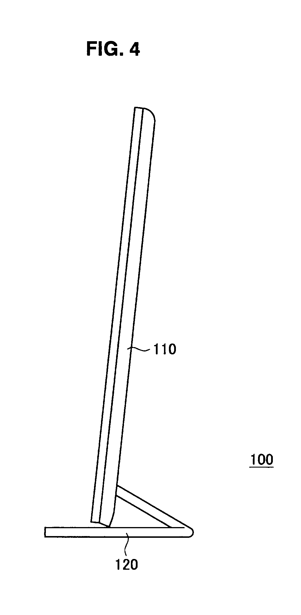
[0044]FIGS. 1, 2, 3, 4, and 5 are schematic views each illustrating an entire structure of a display apparatus 100 according to an embodiment of the present invention. Herein, FIG. 1 is a perspective view of the display apparatus 100. FIG. 2 is a front view of the display apparatus 100. FIG. 3 is a back view of the display apparatus 100 when the display apparatus is seen from the back. FIG. 4 is a right side view of the ...


PUM


Abstract

A display apparatus of present invention includes a tabular display unit having a display screen for displaying an image and a support section constituted by a bent stick member. One end of the support section is inserted into a hole arranged on a back surface of the display unit from a lower side, and the support section is arranged between a placement surface and a lower end of the display unit, whereby the support section supports the display unit from the lower side.

Description

BACKGROUND OF THE INVENTION[0001]1. Field of the Invention[0002]The present invention relates to a display apparatus.[0003]2. Description of the Related Art[0004]In the past, for example, Japanese Patent Application Laid-Open Nos. 2008-129390, 2008-136160, and 2009-122274 describe a known structure for supporting a display panel. In this known structure, a stand is arranged at a lower portion of a thin display apparatus.SUMMARY OF THE INVENTION[0005]However, in the technique disclosed in the above listed patent publications, a relatively large stand is necessary to support a display unit arranged with a display screen. Therefore, there is an issue in that the manufacturing cost of the display apparatus increases. In addition, a visual field of a user would include the large stand arranged outside the display screen, and this causes an issue of reducing the visibility of the display screen.[0006]Moreover, when a product or the like is shipped, it is necessary to pack not only the mai...

Claims


Application Information

Patent Timeline
Patent Type & Authority Patents(United States)
IPC IPC(8): G06F1/16
CPCH05K5/00F16M11/10G06F1/1601F16M2200/08
Inventor SAKAMOTO, TAKESHIMORI, YUSUKEKATSUNUMA, JUN
Owner SATURN LICENSING LLC
Learn More