
Fly-by-wire control system for an aircraft comprising detection of pilot induced oscillations and a control for such a system

a control system and pilot-induced oscillation technology, applied in the direction of process and machine control, instruments, etc., can solve the problems of significant phase shift, return of aerodynamic surfaces, and inability of actuators operating the moving aerodynamic surfaces of aircraft operated from these controls to respond immediately to electric commands generated, etc., to achieve the effect of reducing phase shi

Inactive Publication Date: 2013-06-25
AIRBUS OPERATIONS (SAS)
View PDF19 Cites 2 Cited by
  • Summary
  • Abstract
  • Description
  • Claims
  • Application Information

AI Technical Summary

Benefits of technology

[0012]Thus, by virtue of the present invention, should pilot induced oscillations occur, said control is braked, which alters the feeling of force felt by the pilot (and therefore alerts the pilot to the presence of such oscillations) and reduces the phase shift between the controlled aerodynamic surface and the control.

Problems solved by technology

By contrast, the actuators operating the moving aerodynamic surfaces of the aircraft (ailerons, flaps, rudders, etc.) operated from these controls cannot respond instantly to the electric commands generated by these controls.
There may therefore, at large control amplitudes, be a significant phase shift between the movement of a control and the movement of the moving aerodynamic surfaces it controls.
However, the amplitude of turning of the aerodynamic surfaces may then exceed that corresponding to the initial command, which means that the pilot then reduces the tilt of said control member, thus leading, with a delay, to a return of the aerodynamic surfaces, etc.
Oscillations, caused by coupling and generally referred to in aeronautical parlance as “pilot induced oscillations” (PIO) therefore occur in the aircraft and may degrade the precision of the flying.
In an attempt at solving this problem, it is known practice to increase the size of the actuators of the aerodynamic surfaces controlled and of their electrical and hydraulic supplies, thus increasing the cost and mass of the aircraft.
Such increases in cost and in mass may become intolerable in the case of large-sized aircraft.
However, this processing is Performed without any true detection of the pilot induced oscillations and without the knowledge of the pilot, who may then continue to generate such oscillations.

Method used


Image

  • Fly-by-wire control system for an aircraft comprising detection of pilot induced oscillations and a control for such a system
  • Fly-by-wire control system for an aircraft comprising detection of pilot induced oscillations and a control for such a system

Examples


Embodiment Construction

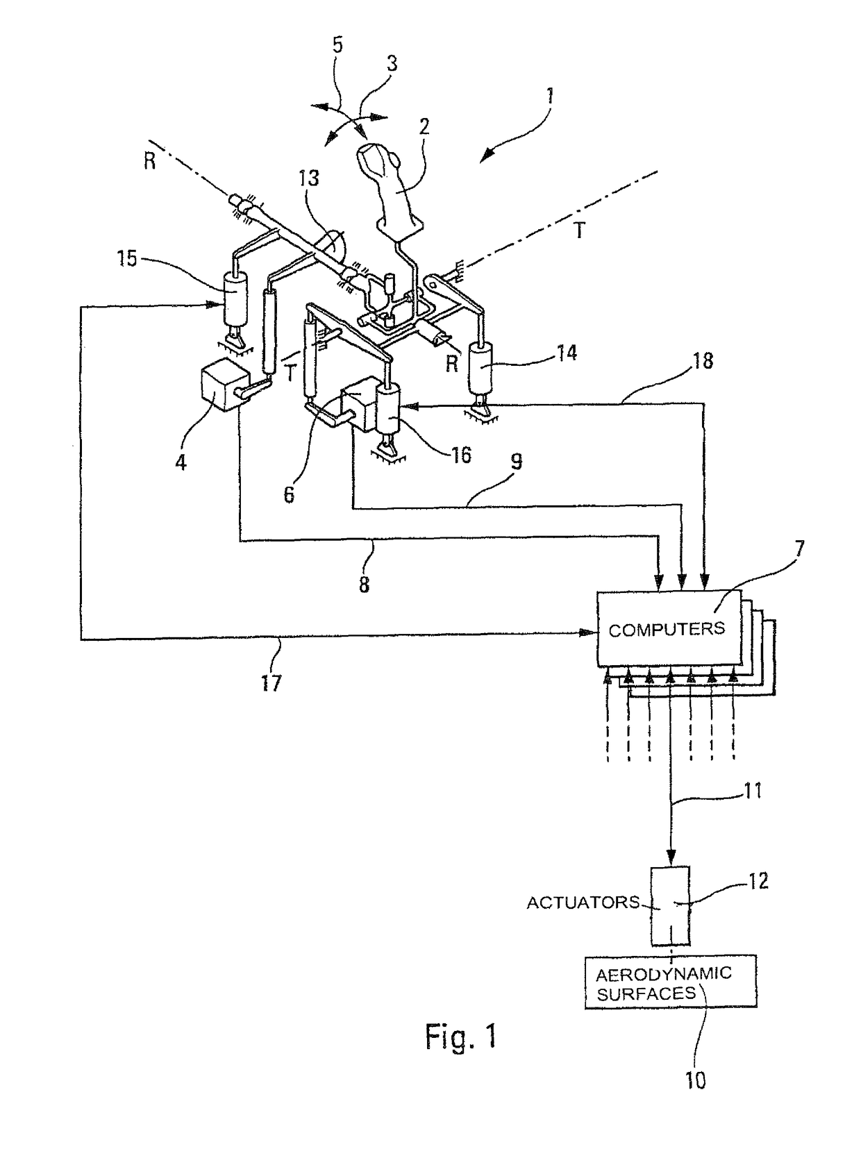
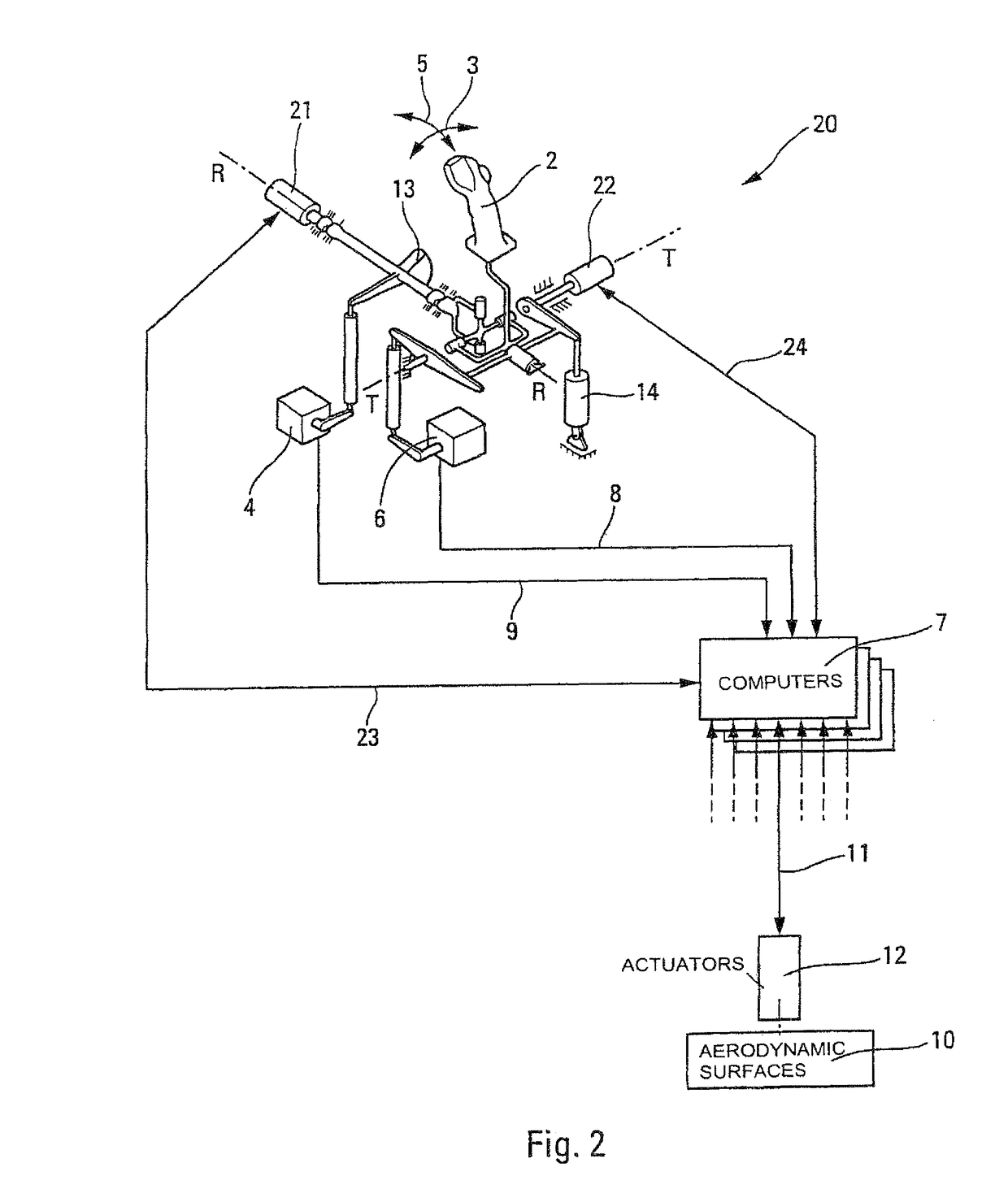
[0024]FIGS. 1 and 2 schematically illustrate two embodiments of the present invention.

[0025]The fly-by-wire control system for an aircraft, illustrated schematically in FIG. 1, comprises a control stick system 1, able to generate a roll command and a pitch command.

[0026]The control stick system 1 comprises a mobile grip 2 which, via a known mechanism, can pivot about a roll-control axis R-R and a pitch-control axis T-T.

[0027]The pivoting of the grip 2 about the roll-control axis R-R (double-headed arrow 3) is detected by a sensor 4. Likewise, the pivoting of the grip 2 about the pitch-control axis T-T (double-headed arrow 5) is detected by a sensor 6.

[0028]The sensors 4 and 6 generate electric commands for roll and pitch, which correspond to the pivotings of the grip 2 and which are sent to the fly-by-wire computers 7 of said system, via lines 8 and 9 respectively. The computers 7 calculate corresponding turn commands for controlled aerodynamic surfaces (flaps, ailerons, rudders, et...


PUM


Abstract

A fly-by-wire control system for an aircraft including detection of pilot induced oscillations and a mobile control unit for such a system. According to the invention, provision is made for the pivotings of the mobile control unit to be damped by a controllable damper controlled by a detector that detects oscillations corresponding to pilot induced oscillations.

Description

[0001]This is a continuation application of application Ser. No. 10 / 703,564 filed Nov. 10, 2003, which is based on French Application No. 02 14388 filed Nov. 18, 2002, the entire contents of each of which are incorporated by reference herein.FIELD OF THE INVENTION[0002]The present invention relates to a fly-by-wire control system for an aircraft comprising detection of pilot induced oscillations, and to a control for such a control system.BACKGROUND OF THE RELATED ART[0003]It is known that the controls (sticks, rudder) of modern aircraft, particularly those known as ministicks, are easy for the pilot and / or the copilot of said aircraft to handle, it being possible for them to be tilted very quickly. By contrast, the actuators operating the moving aerodynamic surfaces of the aircraft (ailerons, flaps, rudders, etc.) operated from these controls cannot respond instantly to the electric commands generated by these controls. There may therefore, at large control amplitudes, be a signifi...

Claims


Application Information

Patent Timeline
Patent Type & Authority Patents(United States)
IPC IPC(8): G01C23/00G05D1/00G05D3/00G06F7/00G06F17/00G05D1/08
CPCG05D1/0816
Inventor RAIMBAULT, NATHALIEGAUTIER, JEAN-PIERRESAGANSAN, ALAINFABRE, PIERRE
Owner AIRBUS OPERATIONS (SAS)
Learn More