Eureka AIR delivers breakthrough ideas for toughest innovation challenges, trusted by R&D personnel around the world.

Suspended ceiling grid system

a grid system and suspended ceiling technology, applied in ceilings, building components, buildings, etc., can solve the problems of requiring specialized components, requiring substantial assembly time and assembly expertise, and being less suitable for complex installations

Active Publication Date: 2013-07-02
CERTAINTEED CANADA
View PDF21 Cites 7 Cited by
  • Summary
  • Abstract
  • Description
  • Claims
  • Application Information

AI Technical Summary

Problems solved by technology

The system works satisfactorily but requires specialized components, substantial installation time and expertise in assembly.
This arrangement is a cost effective solution suitable for rectilinear grid systems and is less suitable for complex installations.

Method used


Image

  • Suspended ceiling grid system
  • Suspended ceiling grid system
  • Suspended ceiling grid system

Examples


Embodiment Construction

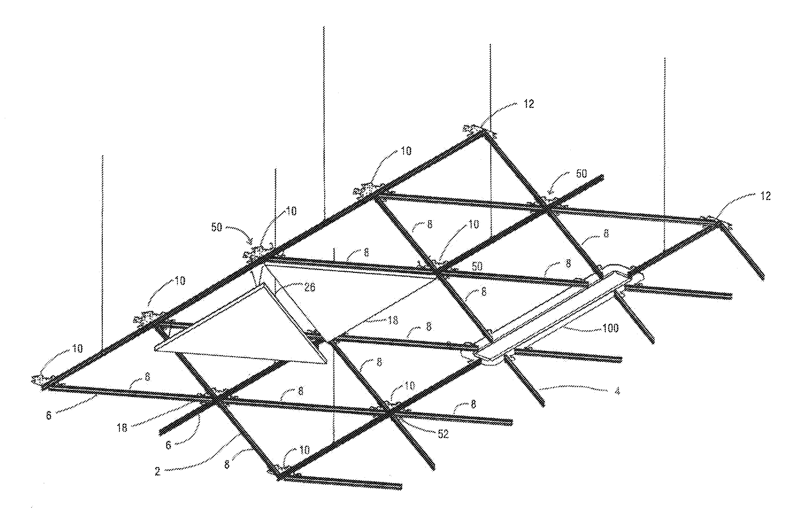
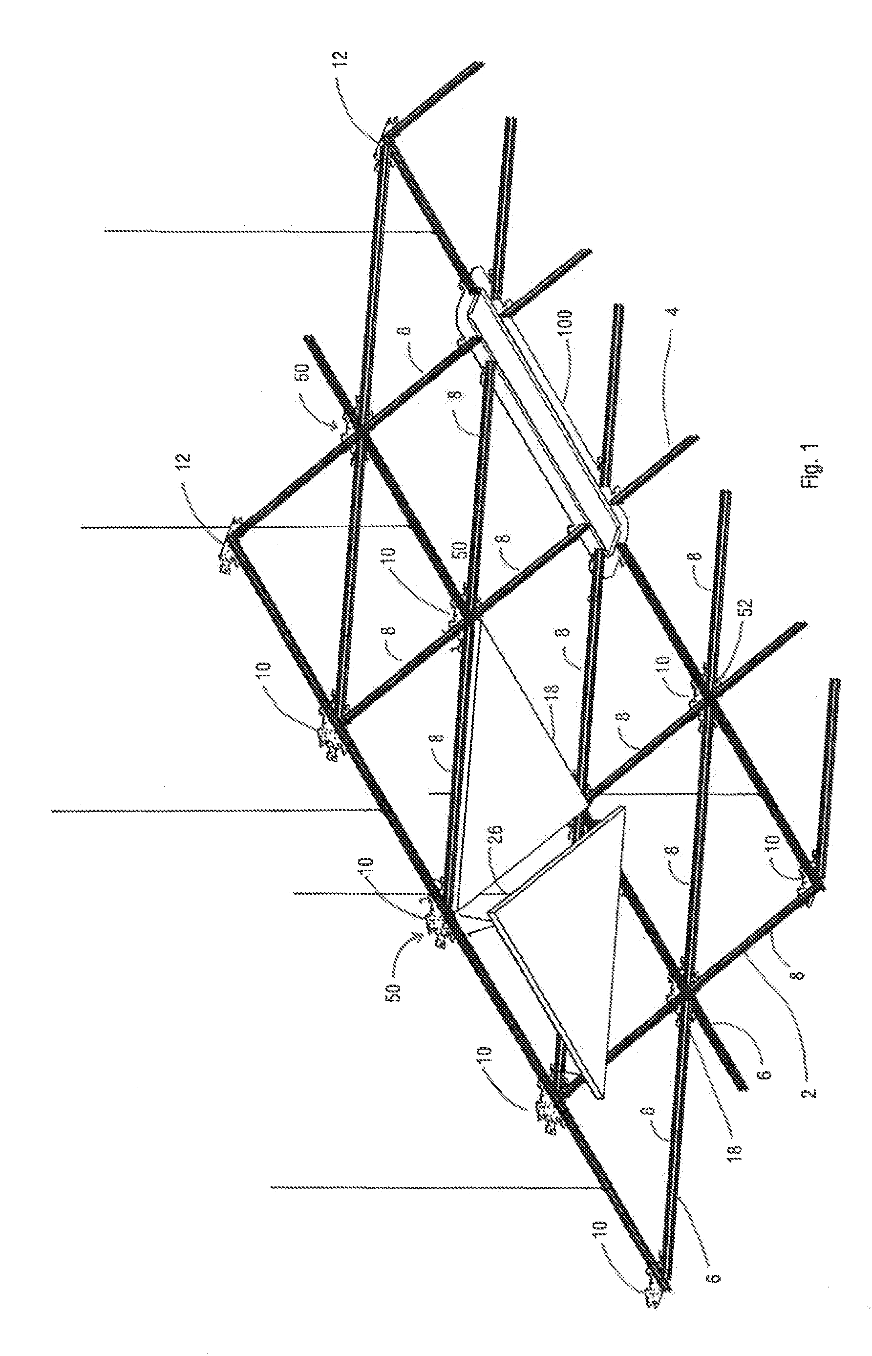
[0048]The suspended ceiling system 2 includes a grid system 4 having ceiling panels 18 suspended there below. The grid system 4 is preferably defined by main grid members 6 which extend through aligned intermediate nodes 10 typically in a length of the ceiling system. Secondary grid members 8 connect adjacent nodes. These secondary grid members 8 are of a short length and do not extend through the center of the intermediate nodes 10. A series of edge nodes 12 are provided at the peripheral edge of the ceiling panel system and as shown these are typically half nodes.

[0049]The suspended ceiling panels 18 are essentially aligned beneath the grid members and preferably the grid members include a downwardly extending flange 76 (see FIGS. 5 and 7) which provides an alignment surface for engaging the edges of the panels, the ceiling panels cover and conceal the grid system. It is preferred that the grid system define individual cells for each panel. Torsion springs 26 are provided near the...


PUM


Abstract

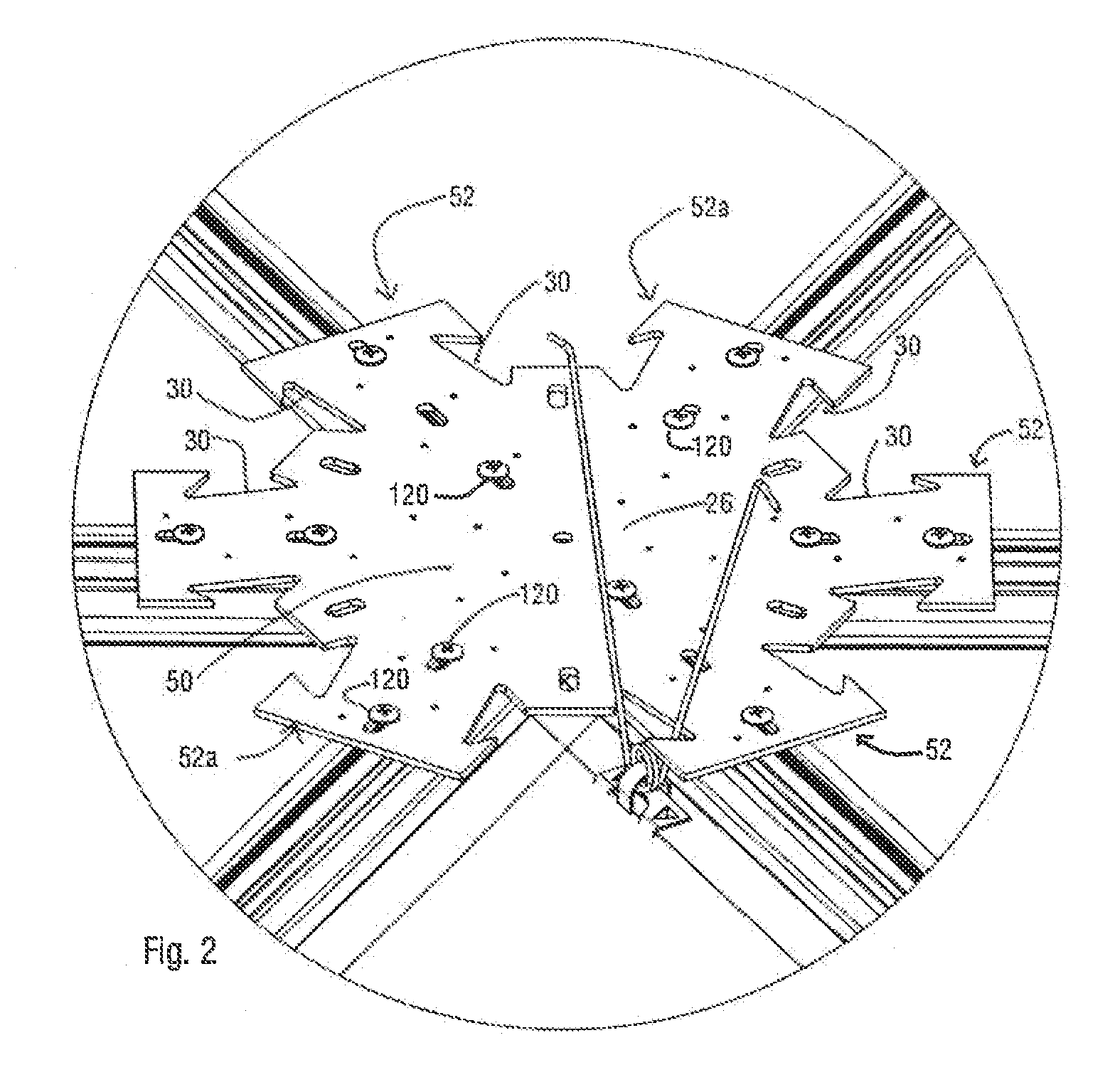
A suspended ceiling system has a series of nodes interconnected by grid members to define a grid network. Each node includes a connection plate having a central port area that is adapted to form a recessed part of the finished surface of the ceiling system that is visible between adjacent suspended ceiling panels that conceal the grid members. The connection plate preferably includes grid member connecting arms extending outwardly from the connection plate. The central port area includes a cavity adapted for different purposes. This cavity can receive ceiling components, for example various light fixtures, securing devices or a removable access panel that covers the central port area.

Description

RELATED APPLICATION[0001]This is a Continuation-In-Part of U.S. application Ser. No. 12 / 659,497 filed Mar. 11, 2010, and is incorporated herein by reference.FIELD OF THE INVENTION[0002]The present application is directed to suspended ceiling systems, and in particular to a grid network used to suspend ceiling panels.BACKGROUND OF THE INVENTION[0003]Examples of suspended ceiling systems are shown in the applicant's earlier U.S. Pat. Nos. 4,436,613 and 5,428,930. The first patent shows a suspended grid system having a series of extruded components that connect to form junction members. These junction members include vertical slots and each individual grid member is received in a slot and secured to the junction member. The individual junction members are suspended from appropriate structural members. Each grid member slidably receives a ceiling panel support bracket along a top edge thereof. These support brackets include slots for receiving extended legs of torsion springs used to su...

Claims


Application Information

Patent Timeline
Patent Type & Authority Patents(United States)
IPC IPC(8): E04C2/52
CPCE04B9/006E04B9/127E04B9/14
Inventor GERKES, MARTIN DANIELKOLGA, HEIKKIWHITE, RONALD
Owner CERTAINTEED CANADA
Why Eureka
Eureka Blog
Learn More