
Method and apparatus for constructing drilling platforms without driven pins

Inactive Publication Date: 2013-07-02
SUPERIOR DERRICK SERVICES
View PDF3 Cites 16 Cited by
  • Summary
  • Abstract
  • Description
  • Claims
  • Application Information

AI Technical Summary

Benefits of technology

The invention is about a drilling platform that can be easily and quickly erected with minimal human labor. It is also safe and economical.

Problems solved by technology

The necessary precision makes for tedious and repetitive adjustments with a crane, raising and lowering the spreader beams until the apertures are aligned precisely.
The required proximity of the workers to and frequent physical contact with the moving steel girders places the workers at risk for injury.
Thus, excessive amounts of time spent constructing the platform foundation can be costly.
Additionally, the high labor requirements of prior art platform construction increases the cost of erecting drilling and service rigs.

Method used


Image

  • Method and apparatus for constructing drilling platforms without driven pins
  • Method and apparatus for constructing drilling platforms without driven pins
  • Method and apparatus for constructing drilling platforms without driven pins

Examples


Embodiment Construction

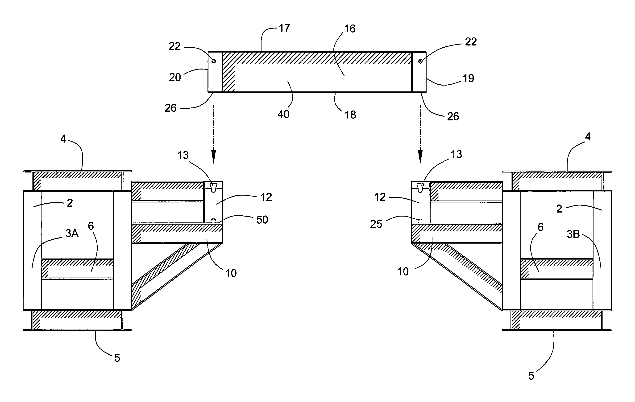
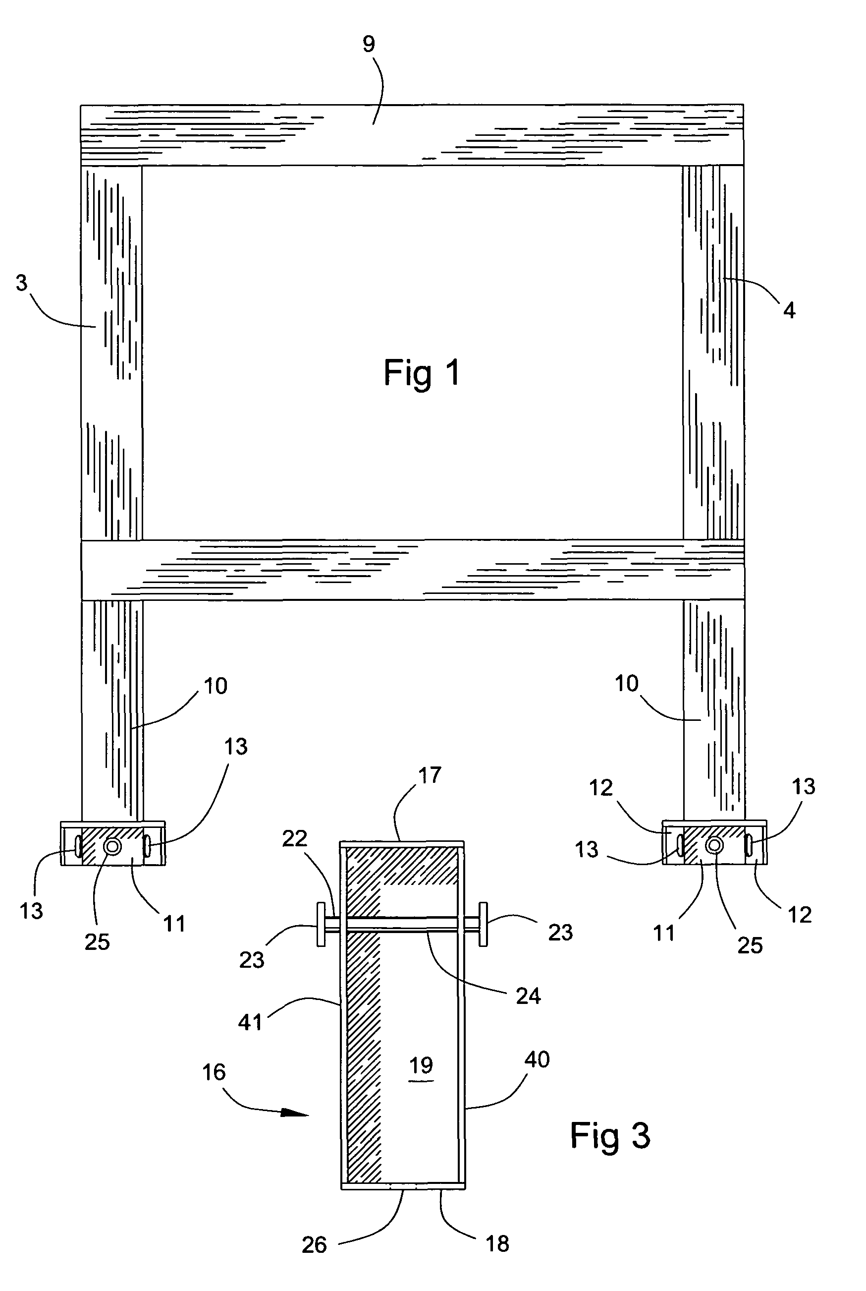
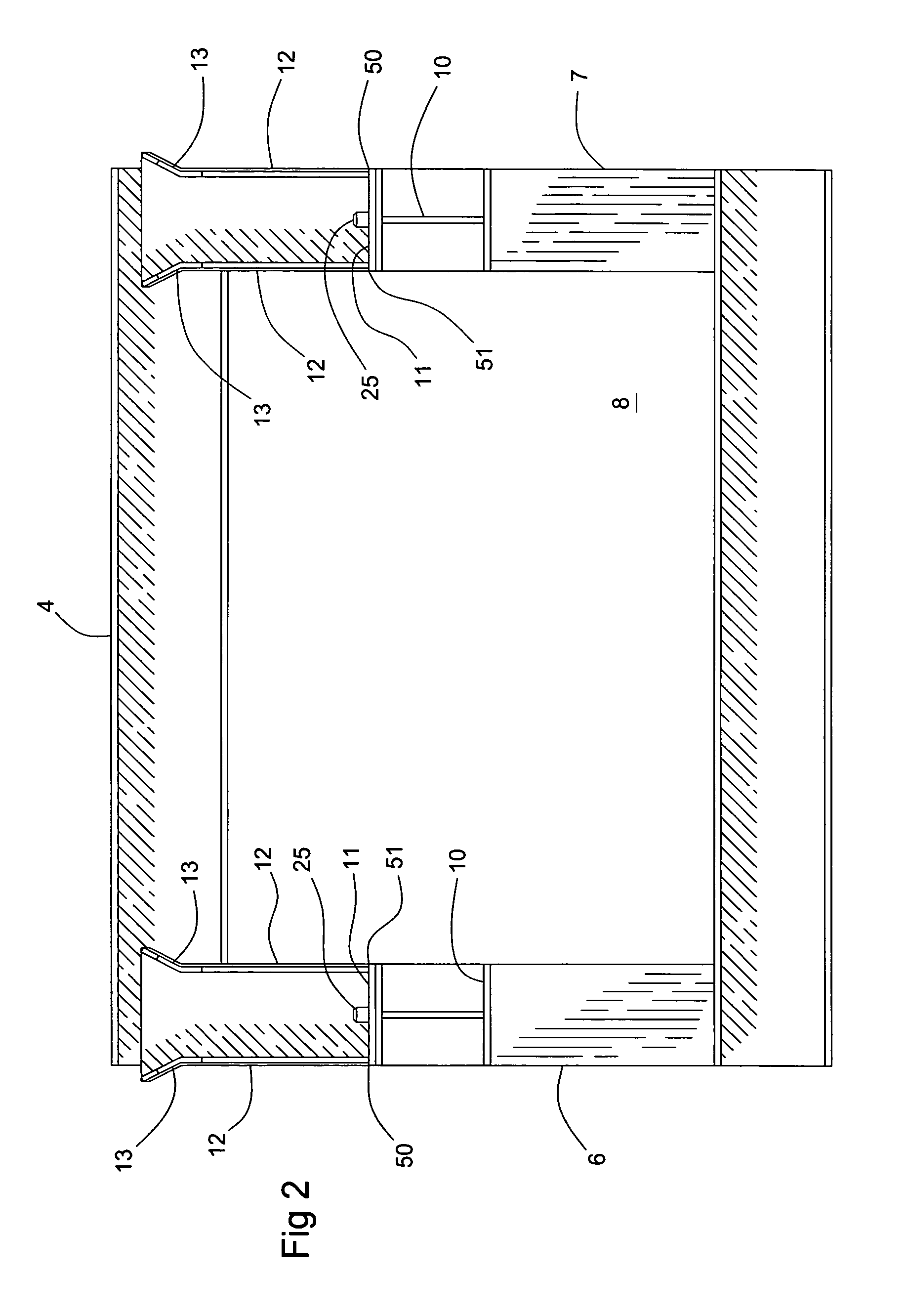
[0027]The preferred embodiment of the invention comprises a drilling platform 1. The drilling platform is comprised of one or more support columns 2. Each support column 2 is comprised of one or more box support members 3. In the preferred embodiment, first and second box support members 3A and 3B are rectangular structures having an upper surface 4 and an opposite lower surface 5. Box support member 3 preferably also has a first end 6 and a second end 7 located opposite first end 6, each end 6, 7 positioned substantially perpendicular to upper surface 4 and lower surface 5. Sides 8 extend between ends 6, 7. Box support member 3 is preferably made of steel beams that have been welded or bolted together to create a load bearing frame 9. Box support members 3 as well as the other components of the invention will need to support substantial amounts of weight. Accordingly, the various components of the present invention should preferably be constructed of 50 ksi or higher steel or simil...


PUM


Abstract

A drilling platform constructed from columns of box support members. Each column has one or more spreader support brackets extending toward another spreader support bracket on an opposite column. Outwardly flaring locking arms rise from the spreader support brackets. A locking aperture is contained in the flared portion of each locking arm. The mouth of the aperture is preferably at about a thirty degree angle to its base so that the mouth is generally facing up. Spreader beams connect the columns. Each spreader beam has a locking pin at each end. The spreader beams are lowered onto the support arms of each column. As they are lowered, the locking pins are aligned to engage the locking apertures and thereby secure the spreader beams to the columns. Once the spreader beams are in place, a work platform can be built on top of the columns and spreader beams.

Description

PRIORITY APPLICATIONS[0001]This application claims priority of U.S. Provisional application 60 / 461,540, filed on Apr. 9, 2003, and which is hereby incorporated by reference in its entirety.BACKGROUND OF THE INVENTION[0002]1. Field of the Invention[0003]This invention relates to drilling platforms in general and drilling platform assemblies in particular.[0004]2. Prior Art[0005]Drilling platforms typically include a one or more box support members. The box support members are usually rectangular steel frameworks. Two or more box support members will often be stacked one upon the other until a desired height is reached. These box supports will be arrayed in parallel columns, leaving a gap between them. The gap will generally include the center line of the well being drilled or serviced. Thus, it is important that the support structure not obstruct the center line of the well. However, it is equally important that the structure be capable of supporting the tools and equipment that are ...

Claims


Application Information

Patent Timeline
IPC IPC(8): E04B1/00
CPCE04H12/10E21B15/00
Inventor GOERNER, DOUGLAS C.
Owner SUPERIOR DERRICK SERVICES
Learn More