
Dispenser of fluid products

a technology of fluid products and dispensers, which is applied in the direction of liquid handling, single-unit apparatuses, and closures using stoppers, etc., can solve the problems of limited dispensing capacity, limited dispensing capacity and intake capacity, and deformation membranes that can sometimes partly block out the outflow of the produ

Active Publication Date: 2013-07-02
APTAR ITAL
View PDF13 Cites 6 Cited by
  • Summary
  • Abstract
  • Description
  • Claims
  • Application Information

AI Technical Summary

Benefits of technology

[0022]In particular, an object of the present invention is to propose a dispenser of fluid products that allows for an improved dispensing capacity.
[0023]Additionally, an object of the present invention is to propose a dispenser of fluid products that is easy and pleasant to use. Lastly, an object of the present invention is to propose a dispenser of fluid products that does not allow unwanted escapes of product. In accordance with the present invention, the technical task and the object described are achieved by a dispenser of fluid products comprising the technical characteristics set out in one or more of the accompanying claims.

Problems solved by technology

Disadvantageously, this type of dispenser is distinguished by a limited dispensing capacity.
Since in known dispensers the dosing chamber presents a considerable minimum volume, the dispensing capacity and the intake capacity are limited and unsatisfactory.
An additional disadvantage of this type of dispensers is associated with the fact that the outflow valve is defined by the combination of the membrane with the dispensing head.
During the dispensing step, the deformed membrane can occasionally partly obstruct the outflow of the product.
This drawback is further reflected in the need for a greater force on the dispensing head to obtain the outflow of the product.
Additionally, among the disadvantages associated with known dispensers there is the impossibility of achieving a delay in the closure of the outflow valve to prevent the escape of drops of product from the nozzle after the completion of the dispensing operation.

Method used


Image

  • Dispenser of fluid products
  • Dispenser of fluid products
  • Dispenser of fluid products

Examples


Embodiment Construction

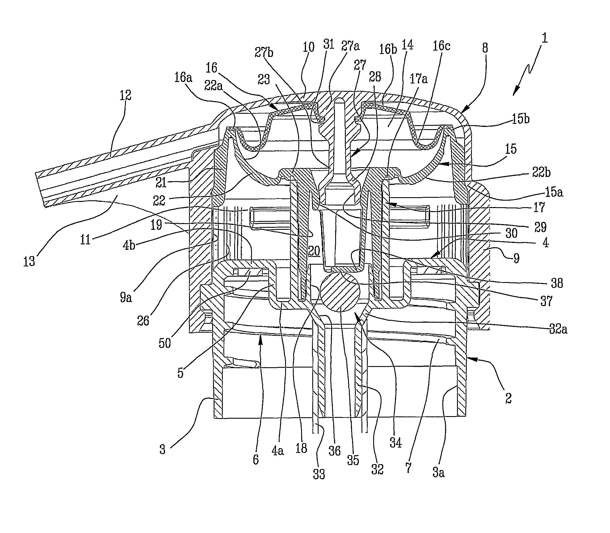
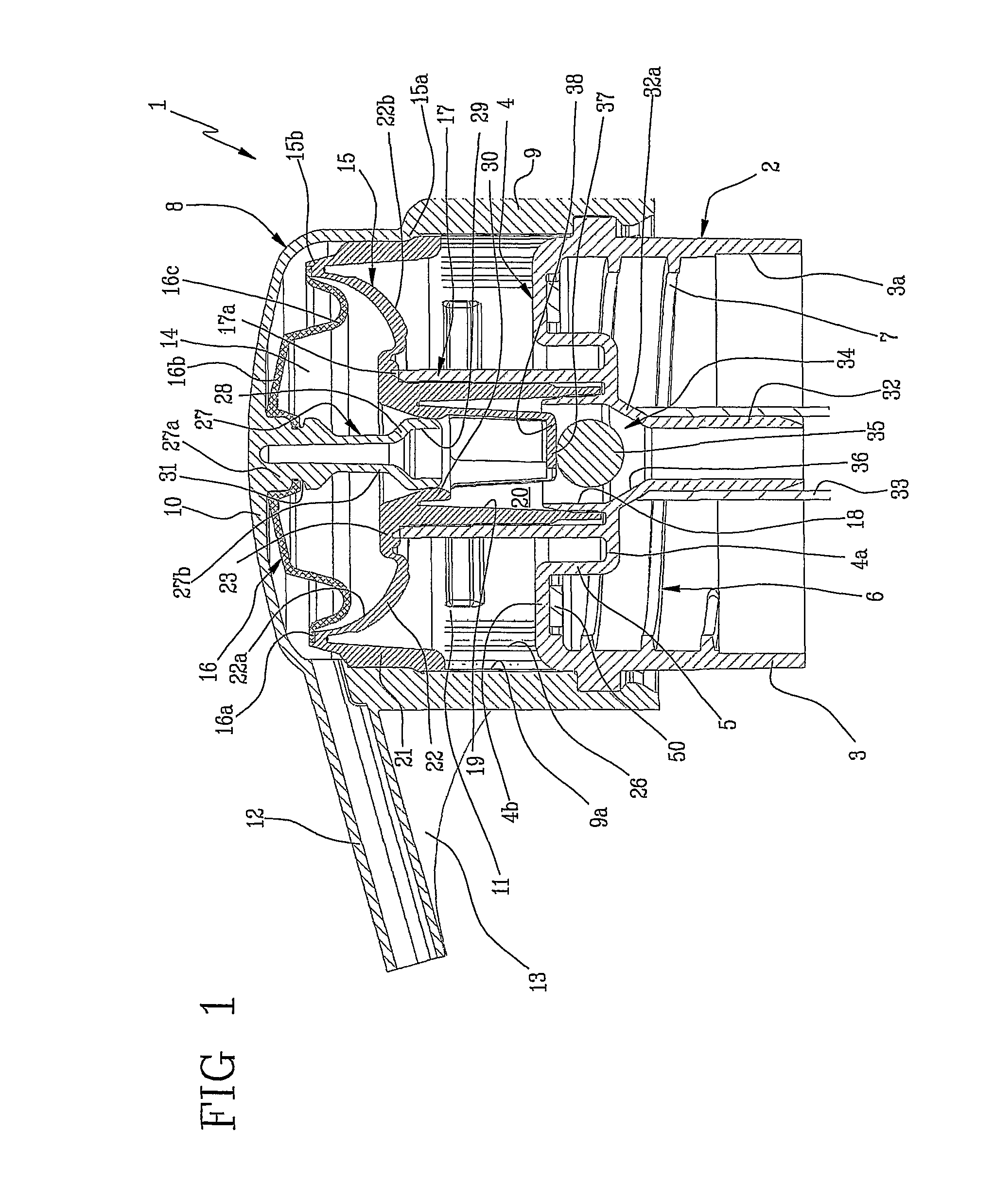
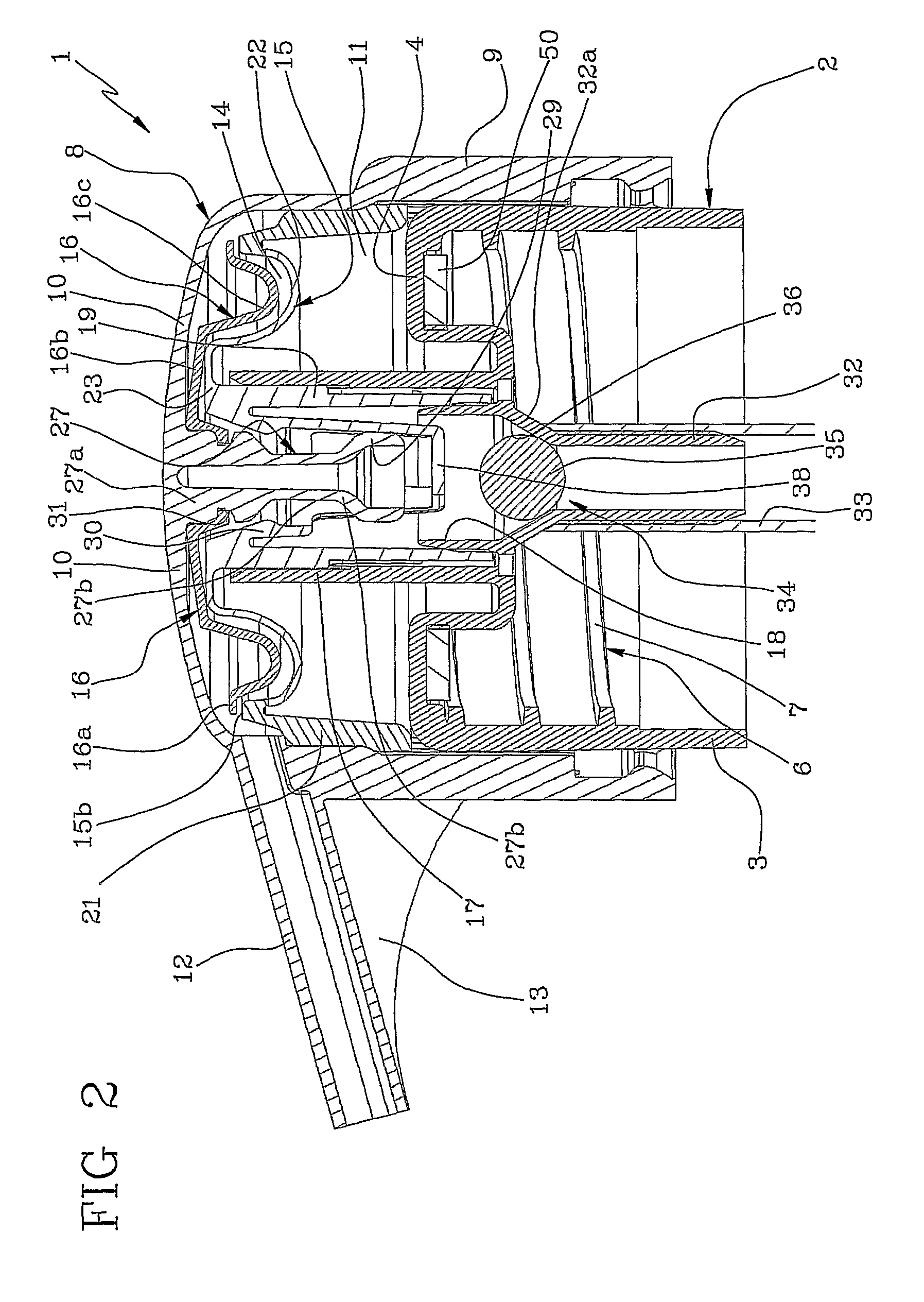
[0031]With reference to the accompanying figures, the number 1 indicates in its entirety a dispenser of fluid products in accordance with the present invention.

[0032]The dispenser 1 comprises a ring nut 2 able to be associated to a container of a fluid product (not shown) comprising a lateral cylindrical wall 3 and an annular wall 4 of the ring nut 2 to obstruct an access to the container.

[0033]The annular wall 4 of the ring nut 2 comprises an inner portion 4a and an outer portion 4b, both flat. The inner portion 4a and the outer portion 4b are parallel and lying on distinct planes. In particular, the inner portion 4b is fully contained in the cylindrical wall 3 of the ring nut 2. The inner portion 4a and the outer portion 4b are connected by means of a cylindrical connecting shoulder 5.

[0034]The ring nut 2 comprises coupling means 6 to fasten the ring nut 2 to the container. In the described embodiment, the coupling means 6 comprise a helical thread 7 obtained on an inner surface 3...


PUM


Abstract

A dispenser of fluid products includes a ring nut (2) able to be associated to a container of a fluid product and a substantially hollow dispensing head, able to slide coaxially relative to the ring nut (2); the dispensing head (8) includes a dosing chamber (14) obtained within the dispensing head (8) and a dispensing nozzle (12) to allow the outflow of the fluid product; the dosing chamber (14) has a containment volume variable between a configuration of maximum volumetric capacity when the dosing chamber (14) is isolated and a configuration of minimum volumetric capacity; the dispenser further includes a deformable membrane (15) fastened to the ring nut (2) and a deformable disc-shaped body (16) fastened to the dispensing head (8) and defining the dosing chamber (14) in combination with the membrane (15).

Description

TECHNICAL FIELD[0001]The present invention relates to a dispenser of fluid products. In particular, the present invention relates to a device for dosing and dispensing viscous fluid products, such as liquid soaps, lotions or the like contained in appropriate containers.BACKGROUND ART[0002]Dispensers of fluid products are known, which close on a container of a fluid product to be dispensed and, therefore, which also serve the function of closing cap for said containers.[0003]Known dispensers comprise a variable volume dosing chamber for aspirating and subsequently dispensing a portion of the fluid product from the container.[0004]In detail, when the volume of the dosing chamber is reduced, the overpressure thus produced expels outwards the portion of fluid portion contained therein, whilst when the volume of the dosing chamber is increased the vacuum thus created aspirates a subsequent portion of product from the container to the dosing chamber. Appropriate check valves regulate the ...

Claims


Application Information

Patent Timeline
Patent Type & Authority Patents(United States)
IPC IPC(8): B65D37/00B67B1/00
CPCB05B11/007B05B11/3028B05B11/1028
Inventor CARTA, LAMBERTO
Owner APTAR ITAL
Learn More