Adjustable excision device for bones

a technology of excision device and adjustment, which is applied in the field of adjustable excision device for bones, can solve the problems of difficult to maintain accurate parallelism between cuts, increase recovery period, and severe injuries to patients, and achieve the effect of less chance and erroneous shortening of bones

a technology of excision device and adjustment, which is applied in the field of adjustable excision device for bones, can solve the problems of difficult to maintain accurate parallelism between cuts, increase recovery period, and severe injuries to patients, and achieve the effect of less chance and erroneous shortening of bones

US8475462B2Inactive Publication Date: 2013-07-02THOMAS GARETH +2

Image

  • Adjustable excision device for bones
  • Adjustable excision device for bones
  • Adjustable excision device for bones

Examples


Embodiment Construction

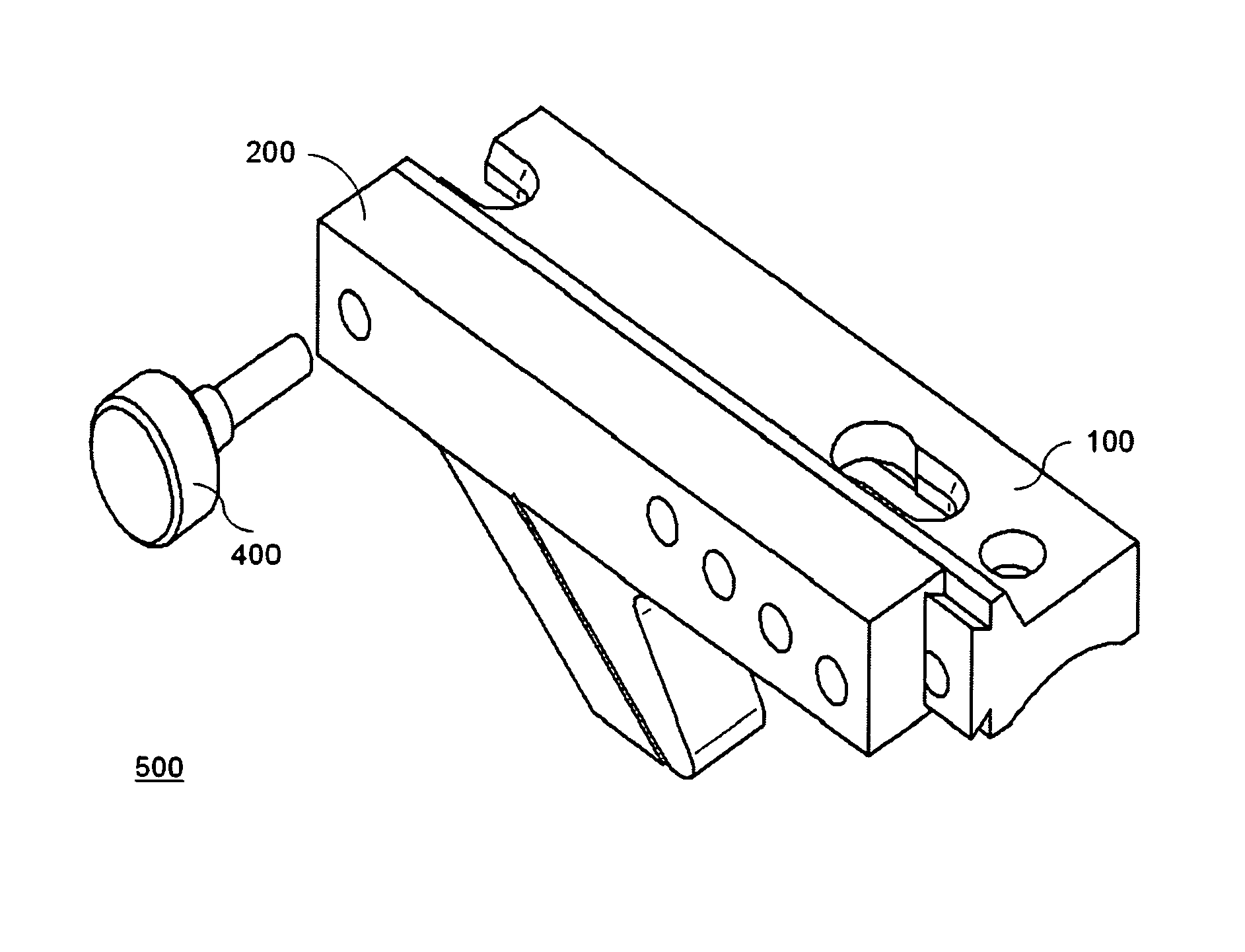
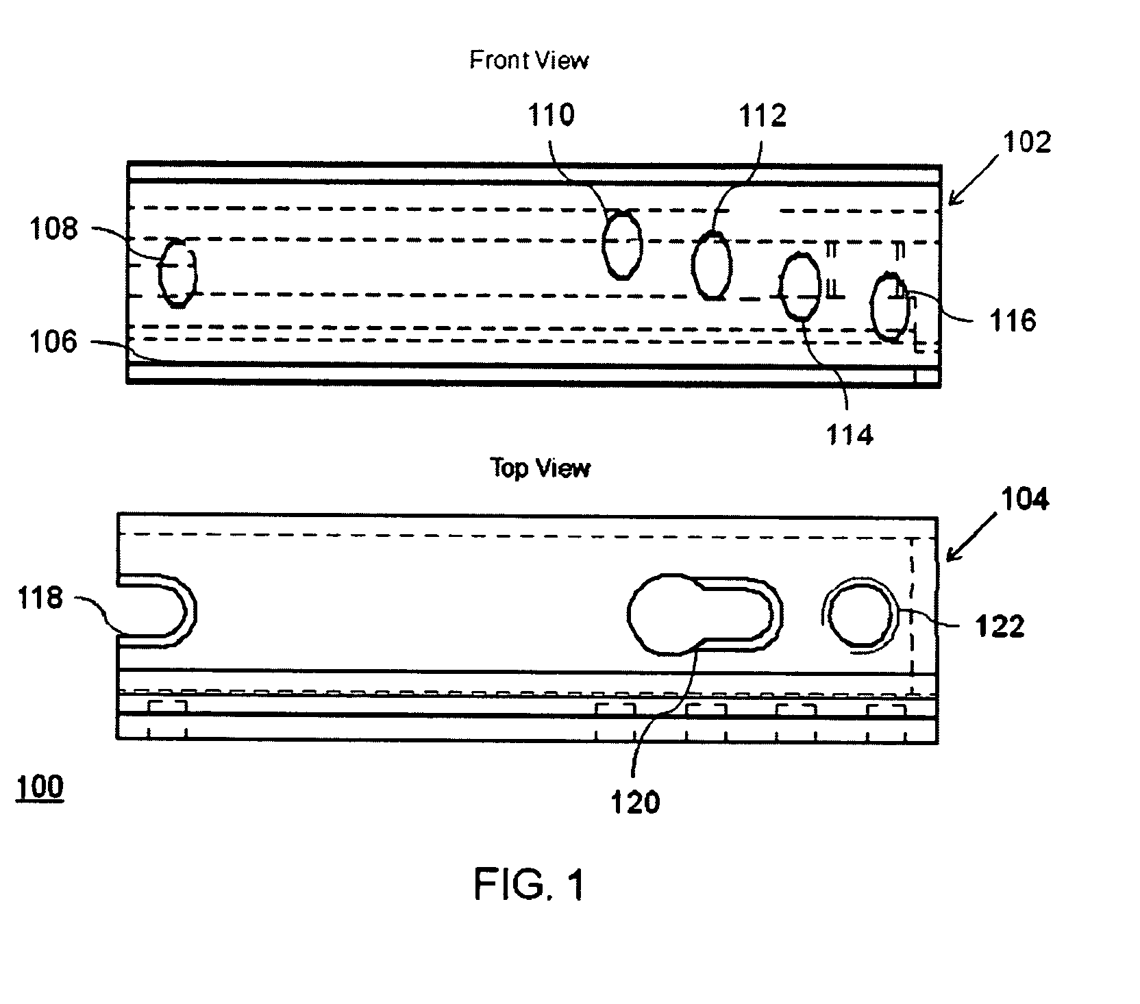
[0031]Referring to the Figures, FIG. 1 is an orthographic projection of a support block 100 viewed from front and top in accordance with an embodiment of the present invention. The support block 100 is generally a block having at least a front surface 102 and a top surface 104. The front surface 102 of the support block 100 includes a dovetail joint 106. The dovetail joint 106 is integrally formed on the front surface 102 of the support block 100.

[0032]In an alternate embodiment, the dovetail joint 106 may also be formed as a separate unit and is adapted to be connected to front surface 102. Further, the dovetail joint 106 includes at least one recess 108. Further recesses are shown as 110, 112, 114 and 116. Said recesses 108, 110, 112, 114 and 116 generally have a circular shape. However, the shape of the one or more recesses 108, 110, 112, 114 and 116 can also be square, rectangular, slot or oval or any other suitable shape.

[0033]Further, the one or more recesses 108, 110, 112, 11...


PUM


Abstract

The present invention provides a device for segmenting a bone. The bone is segmented in two cuts i.e. an initial cut and a final cut. While segmenting the bone, the device is clamped to the bone directly or with the help of a block attached to the bone. An initial cut is taken after the clamping is performed. An upper part of the device is then moved to a predetermined length and the final cut is taken. Thus, the device enables an accurate length of cut to be taken while segmenting the bone. The device also enables varied length of cuts to be taken while segmenting the bone.

Description

FIELD OF THE INVENTION[0001]The present invention relates to an adjustable excision device for bones.BACKGROUND OF THE INVENTION[0002]Osteotomy is a surgical procedure generally used for relieving pain in arthritis, to align a bone which bulges abnormally following a fracture or to shorten or lengthen the bone. Osteotomy involves making singular or multiple cuts into the bone followed by removal of a piece of bone present near a damaged joint.[0003]The piece of bone is typically removed by segmenting the bone with the use of a cutter.[0004]A variety of surgical techniques are required for segmenting a piece of bone. The success of the variety of surgical techniques relies on the preciseness with which a cut is made. An imprecise cut can often lead to severe injuries to patients. Even, unnecessary trauma can be caused to tissues surrounding the piece of bone leading to an increased recovery period.[0005]Generally, cutting guides are employed for straight accurate cuts while performin...

Claims


Application Information

Patent Timeline
02 Jul 2013
Publication
US8475462B2
IPC
A61B17/60; A61F2/00
CPC
A61B17/15; A61B17/151
Inventors
THOMAS, GARETH; KNOX, PAUL