Overvoltage protection element

a protection element and overvoltage technology, applied in the direction of emergency protective arrangements for limiting excess voltage/current, spark gap details, circuit arrangements, etc., can solve the problems of solder connection melting and solder connection continuously loaded with shear stress, and achieve reliable and good electrical connection

Inactive Publication Date: 2013-07-09
PHOENIX CONTACT GMBH & CO KG
View PDF14 Cites 2 Cited by
  • Summary
  • Abstract
  • Description
  • Claims
  • Application Information

AI Technical Summary

Benefits of technology

[0010]A primary object of this invention is, therefore, to provide an overvoltage protection element of the initially described type in which the aforementioned disadvantages are avoided, i.e., both a reliable and good electrical connection in the normal state and also reliable isolation of a defective overvoltage limiting component will be ensured and an insulation and tracking resistance as high as possible will be achieved, even with a size of the overvoltage protection element that is as small as possible.
[0011]This object is achieved in an overvoltage protection element of the initially described type in that the overvoltage limiting component is pivotally mounted in the housing, in the normal state of the overvoltage protection element at least one pole of the overvoltage limiting component being connected to one connecting element via a plug-and-socket connection. Moreover, at least one spring element is located between the housing and the overvoltage limiting component such that the overvoltage limiting component when thermally overloaded is turned by the spring element such that at least one pole is no longer in electrically conductive contact with the assigned connecting element. So that, in the overvoltage protection element in accordance with the invention, the two poles of the overvoltage limiting component, in the normal state of the overvoltage protection element, are in electrically conductive contact with the connecting elements against the spring force of the spring element, and between the overvoltage limiting component and the housing, there is a thermally separating connection which separates when the temperature of the overvoltage limiting component exceeds a given boundary temperature. In the normal state of the overvoltage protection element, this connection between the overvoltage limiting component and the housing prevents rotation of the overvoltage limiting component so that the connecting elements are each in electrically conductive contact with one pole of the overvoltage limiting component.
[0017]The formation of two plug-and-socket connections leads to there also being two gaps. In this way, the extinguishing of an arc which may occur on the gaps is promoted since the two gaps form a series connection so that the overall arc length and thus also the arc voltage are increased by the series connection of the two gaps.
[0019]Preferably, the second pole of the overvoltage limiting component is connected to a pivot and the respective second connecting element on the side facing the pivot is connected to the corresponding rotary support arrangement. The execution of a rotary connection between the second pole of the overvoltage limiting component and the second connecting element makes it possible for the overvoltage limiting component to be turned by the spring element when the latter component is thermally overloaded. In this configuration, in case of damage to the overvoltage limiting component, only one pole is separated from the connecting element, while the other pole is still connected to the connecting element by way of a rotary connection.

Problems solved by technology

If unallowable heating of the varistor occurs, this leads to melting of the solder connection.
However, the problem here is that the solder connection is continuously loaded with a shear stress as a result of the spring force of the spring element or of the disconnection tongue which has been deflected out of its rest position in the normal state of the overvoltage protection element.

Method used


Image

  • Overvoltage protection element
  • Overvoltage protection element
  • Overvoltage protection element

Examples


Embodiment Construction

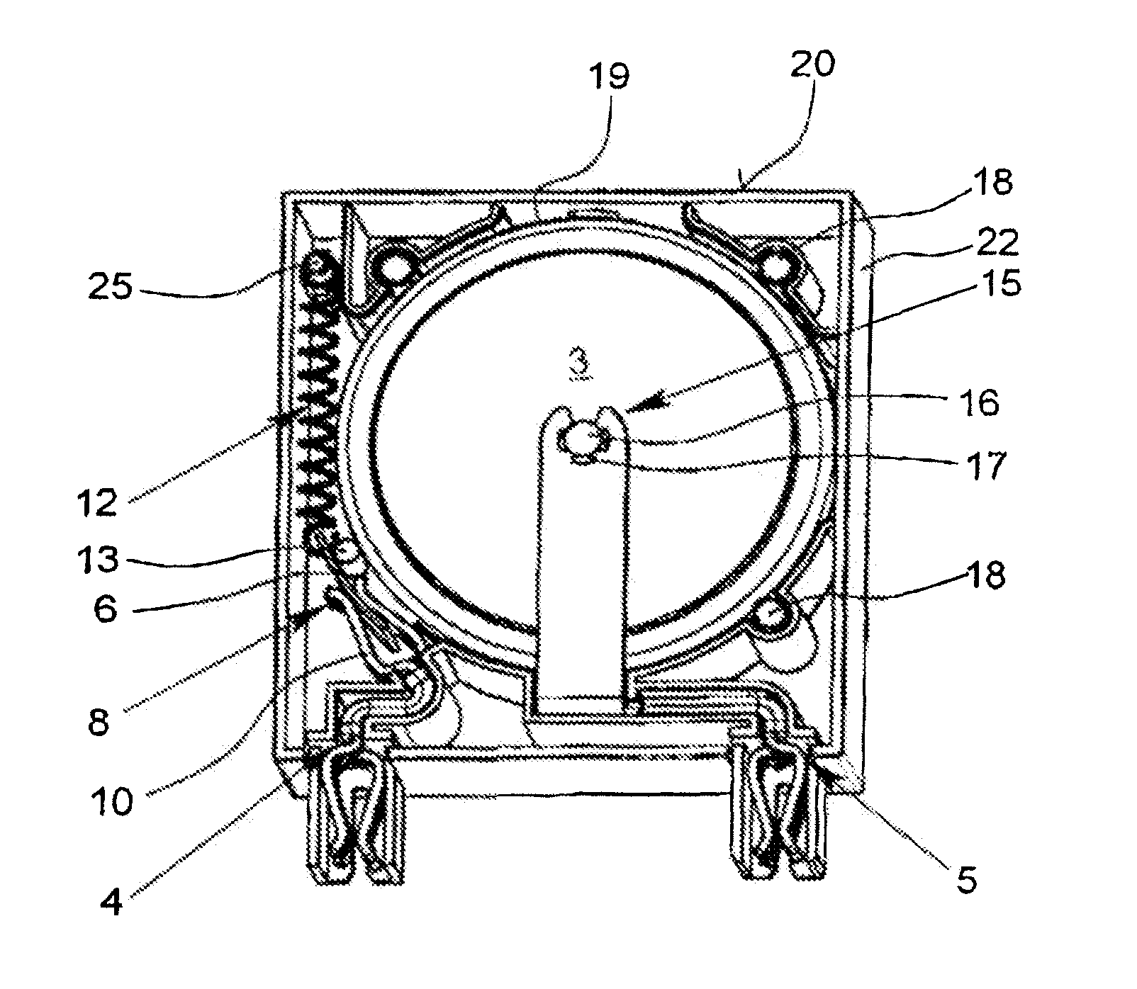
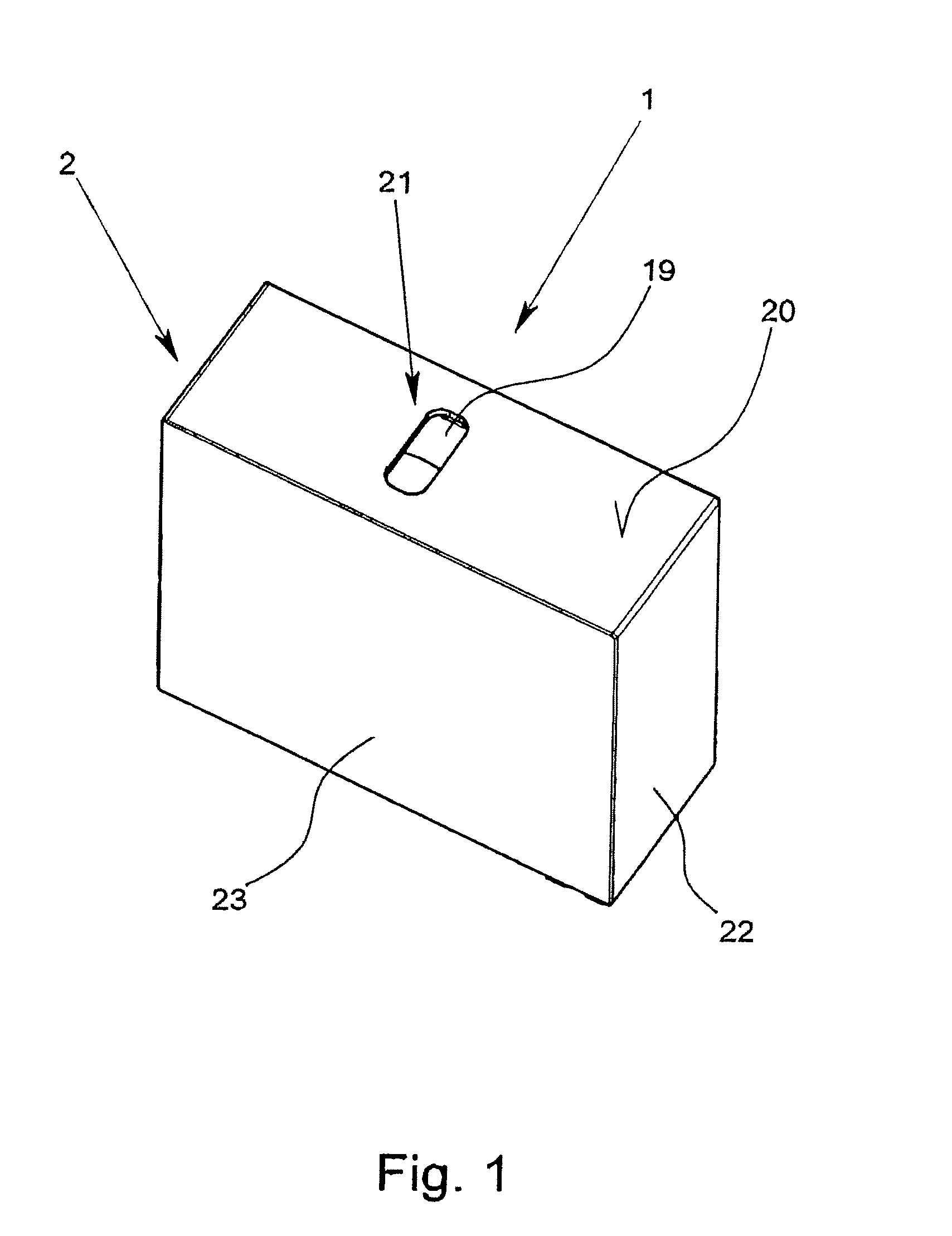
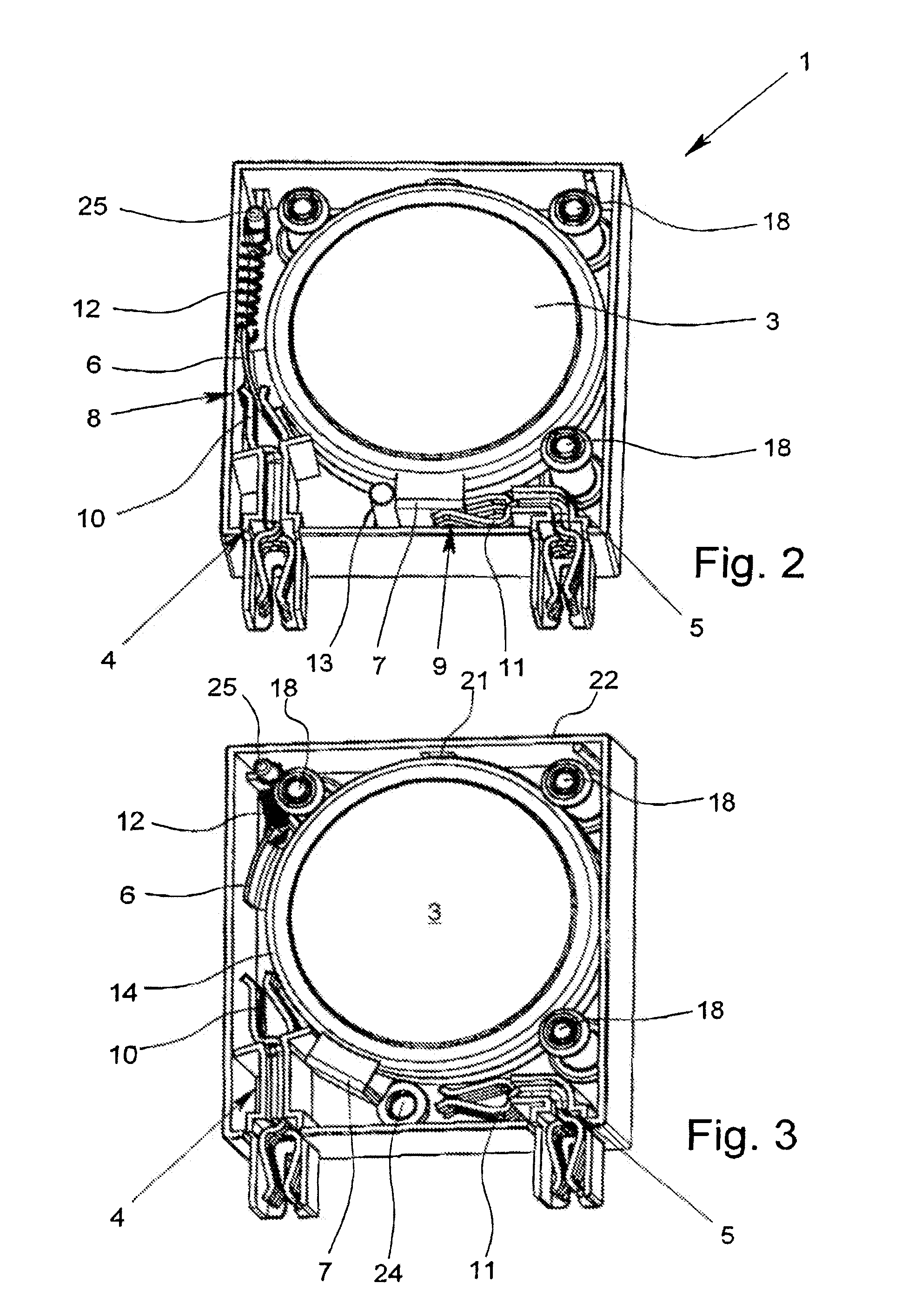
[0028]The figures show an overvoltage protection element 1 with a housing 2 in the which there is an overvoltage limiting component 3. In the illustrated exemplary embodiments, the overvoltage limiting component is a varistor 3; alternatively, for example, a gas-filled surge arrester can also be used as an overvoltage limiting component 3. The overvoltage protection element 1, which is made as a “protective plug”, has two connecting elements 4, 5 which are made as sockets and which can be plugged onto the corresponding plug pins of the lower part of the device (shown here).

[0029]In the exemplary embodiment as shown in FIGS. 2 and 3, the two poles of the varistor 3 are each connected to a terminal lug 6, 7. In the normal state of the overvoltage protection element 1, the varistor 3 is connected to the two connecting elements 4, 5 via the two terminal lugs 6, 7. The connection between the two terminal lugs 6, 7 and the two connecting elements 4, 5 follows by way of a plug-and-socket c...


PUM


Abstract

An overvoltage protection element with a housing, at least one overvoltage limiting component in the housing, especially a varistor, and two connecting elements for electrically connecting the overvoltage protection element to a current or signal path in a normal state, the connecting elements being in electrically conductive contact with a respective pole of the overvoltage limiting component. In the normal state of the overvoltage protection element, at least one pole is connected to a connecting element via a plug-and-socket connection, and at least one spring is located between the housing and the overvoltage limiting component such that, when the overvoltage limiting component is thermally overloaded, it is turned by the spring separating the at least one pole from the assigned connecting element, and creating a thermally separating connection between the overvoltage limiting component and the housing when the temperature of the overvoltage limiting component exceeds a given boundary temperature.

Description

BACKGROUND OF THE INVENTION[0001]1. Field of the Invention[0002]The invention relates to an overvoltage protection element with a housing, at least one overvoltage limiting component which is located in the housing, especially a varistor, and with two connecting elements for electrical connection of the overvoltage protection element to the current path or signal path to be protected, in the normal state of the overvoltage protection element, the connecting elements each being in electrically conductive contact with one pole of the overvoltage limiting component.[0003]2. Description of Related Art[0004]German Patent DE 42 41 311 C2 discloses an overvoltage protection element which has a thermal disconnector for monitoring the state of a varistor. In this overvoltage protection element, the first connecting element is connected via a flexible conductor to a rigid disconnection element whose end facing away from the flexible conductor is connected via a solder point to a terminal lug ...

Claims


Application Information

Patent Timeline
Patent Type & Authority Patents(United States)
IPC IPC(8): H02H1/00H02H3/22H02H3/20
CPCH01T1/12H01C7/126H01T1/14
Inventor GREWE, CHRISTINAMETZGER, ANDREAS
Owner PHOENIX CONTACT GMBH & CO KG
Why Eureka
Try Eureka