Overvoltage protection element

a protection element and overvoltage technology, applied in the direction of emergency protective circuit arrangements, emergency protective arrangements for limiting excess voltage/current, emergency protective arrangements, etc., can solve the problem of limit of the maximum allowable impulse current which can be discharged by the overvoltage protection element, limit the maximum allowable impulse current, and melt of the solder connection, etc. problem, to achieve the effect of reliable and good electrical connection and reliable isolation of defective overvoltage limiting components

Inactive Publication Date: 2013-07-02
PHOENIX CONTACT GMBH & CO KG
View PDF15 Cites 8 Cited by
  • Summary
  • Abstract
  • Description
  • Claims
  • Application Information

AI Technical Summary

Benefits of technology

[0011]A primary object of this invention is, therefore, to provide an overvoltage protection element of the initially described type in which the aforementioned disadvantages are avoided. More specifically, both a reliable and good electrical connection in the normal state and also reliable isolation of a defective overvoltage limiting component will be ensured. Moreover, an insulation and tracking resistance that is as high as possible with an overall size of the overvoltage protection element as small as possible will be achieved so that the overvoltage protection element can discharge impulse currents as high as possible.
[0014]According to one preferred configuration of the invention, the insulating disconnecting element is formed by a rigid insulator plate and the conductive connecting element is formed by at least one metal piece, the metal piece preferably being pressed in an opening which is made in the insulating plate. The insulating disconnecting element and the conductive connecting element are connected tightly to one another and form a joint component, by which, on the one hand, mounting of the overvoltage protection element is simplified and, on the other hand, it is ensured that the conductive connecting element and the insulating disconnecting element always move jointly.
[0015]According to another advantageous configuration of the invention, the second terminal contact is permanently connected to a rigid metallic terminal element, in the normal state of the overvoltage protection element the end of the rigid metallic terminal element facing away from the second terminal contact being connected via a thermally separating connection, i.e., via a solder connection, to one side of the conductive connecting element. The rigid metallic terminal element can be dimensioned such that it can also easily transmit impulse currents with very high amplitudes. In the normal state of the overvoltage protection element the second pole of the overvoltage limiting component or a terminal lug connected to the pole is soldered to one side of the connecting element and the rigid metallic terminal element is soldered to the other side of the connecting element so that the second terminal contact is connected in an electrically conductive manner via the metallic terminal element and the connecting element to the second pole of the overvoltage limiting component or the terminal lug of the second pole.
[0022]According to a last advantageous configuration of the overvoltage protection element in accordance with the invention, which is briefly described here, there is an optical state display which indicates whether the overvoltage limiting component located in the overvoltage protection element is still serviceable or not. For this purpose, on the tripping slide there is preferably a colored display surface, depending on the position of the tripping slide, the display surface or a certain region of the display surface being located underneath a viewing window made in the housing. The viewing window can be made preferably in the top of the housing so that the state display can also be easily read when the overvoltage protection device is locked on a mounting rail.

Problems solved by technology

The level of the maximum allowable impulse current which can be discharged by the overvoltage protection element is limited by the use of the flexible conductors to connect the varistor.
If undue heating of the varistor occurs, this leads to melting of the solder connection.
However, this likewise leads to limitation of the maximum allowable impulse current.
Here, undue heating of the varistor also leads to heating of the solder site so that the slide is withdrawn from the connecting site between the first terminal element and the terminal lug as a result of the force of a spring acting on it; this leads to electrical isolation of the varistor.

Method used


Image

  • Overvoltage protection element
  • Overvoltage protection element
  • Overvoltage protection element

Examples


Embodiment Construction

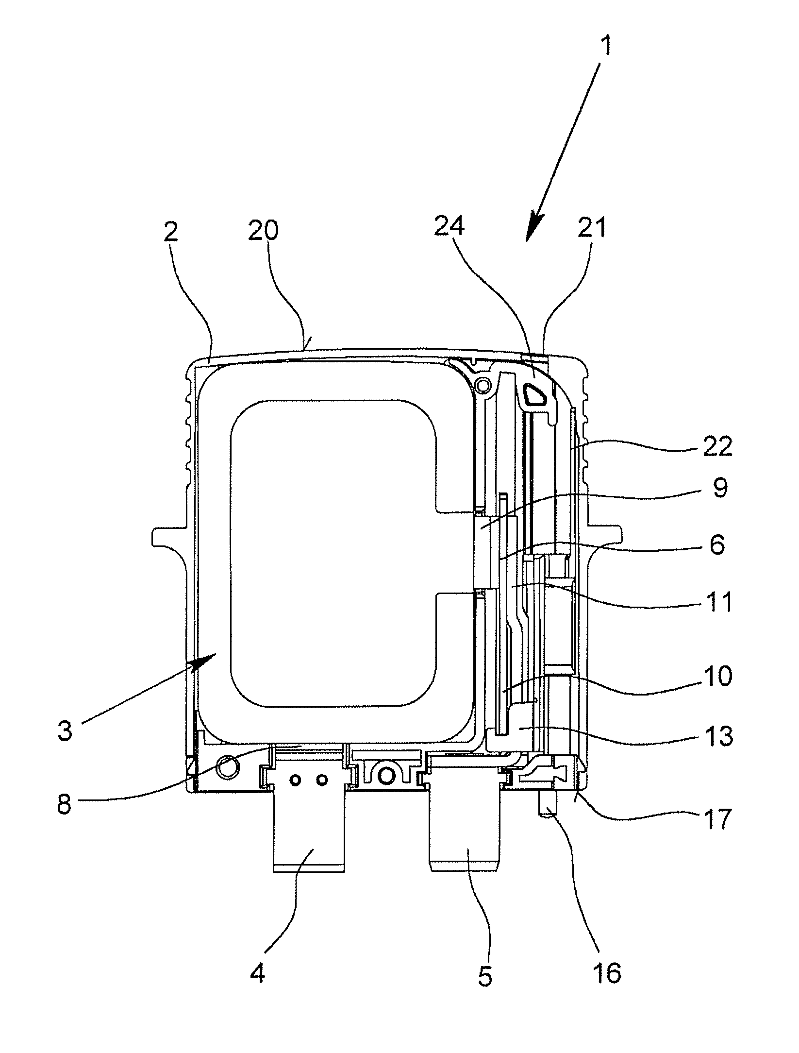
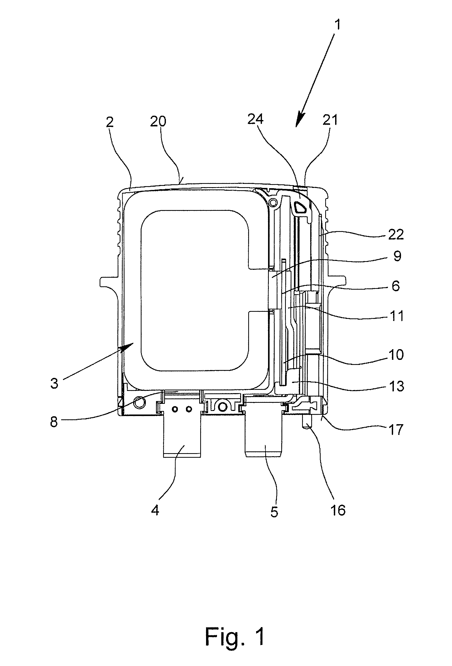
[0028]The figures show an overvoltage protection element 1 with a housing 2, there being an overvoltage limiting component 3 in the housing 2. In the illustrated exemplary embodiments, the overvoltage limiting component is a varistor 3; alternatively, the overvoltage limiting component 3 can also be a double varistor or a gas-filled surge arrester, for example. The overvoltage protection element 1, which is made as a protective plug, has two terminal contacts 4, 5 which are made as knife-edge contacts and which can be plugged into the corresponding sockets of a device bottom part (not shown here).

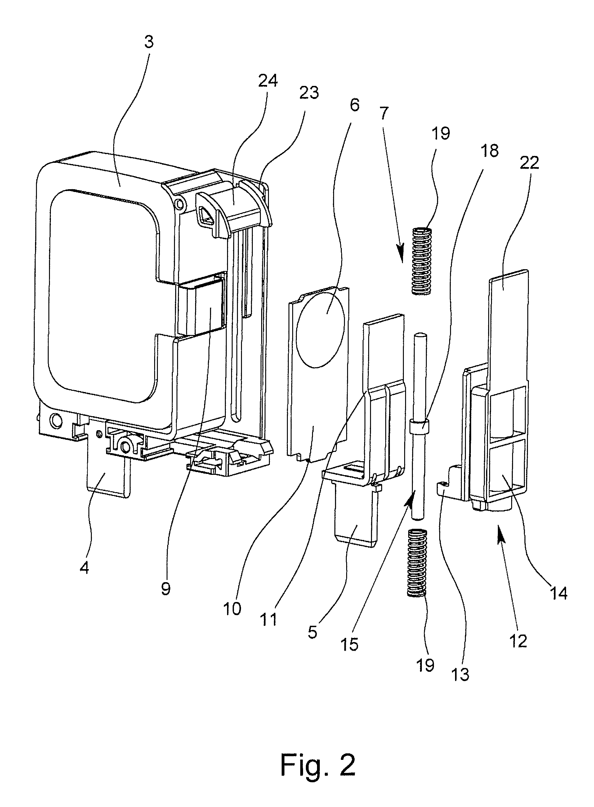
[0029]As is especially apparent from the exploded representation as shown in FIG. 2, the overvoltage protection element 1 also has a conductive connecting element 6 and a spring system 7. The two poles of the varistor 3 are each connected to a respective terminal lug 8, 9, in the normal state of the overvoltage protection element 1, the varistor 3 being connected to the two terminal contact...


PUM


Abstract

An overvoltage protection element having at least one overvoltage limiting component in a housing, terminal contacts for electrical connection of the overvoltage protection element to a path to be protected, an electrically conductive connecting element and with a spring system acting on the connecting element, a first terminal contact being directly connected with the first pole of the overvoltage limiting component, the connecting element being in electrically conductive contact with the second terminal contact and the second pole of the overvoltage limiting component via a thermally separating connection. With the thermal connection separated, the connecting element moves out of electrically conductive contact with the second terminal contact and the second pole of the overvoltage limiting component by the force of the spring system an insulating disconnecting element connected to the connecting element is moved between the second terminal contact and the second pole of the overvoltage limiting component.

Description

BACKGROUND OF THE INVENTION[0001]1. Field of the Invention[0002]The invention relates to an overvoltage protection element with a housing, with at least one overvoltage limiting component which is located in the housing, especially a varistor, with two terminal contacts for electrical connection of the overvoltage protection element to the current path or signal path to be protected, with an electrically conductive connecting element and with a spring system which acts on the connecting element, the first terminal contact being in electrically conductive contact directly with the first pole of the overvoltage limiting component, in the normal state of the overvoltage protection element the connecting element being in electrically conductive contact both with the second terminal contact and also with the second pole of the overvoltage limiting component via a thermally separating connection which separates when the temperature of the overvoltage limiting component exceeds a given bou...

Claims


Application Information

Patent Timeline
Patent Type & Authority Patents(United States)
IPC IPC(8): H02H5/04H02H1/04
CPCH01H37/761H01H2037/762
Inventor DEPPING, CHRISTIANTEGT, MICHAELWOSGIEN, JOACHIMPHILIPP, MARKUS
Owner PHOENIX CONTACT GMBH & CO KG
Why Eureka
Try Eureka