Radar system

a radar system and crawler technology, applied in the field of radar systems, can solve the problems of difficult, if not impossible, to distinguish crawler from clutter, inability to utilise doppler radar systems, and traditional crawler radar systems are inherently limited to maximum detection ranges, so as to increase the range resolution and reduce the relative power of clutter, the effect of increasing the resolution of doppler and range ga

Active Publication Date: 2011-01-25
BLIGHTER SURVEILLANCE SYST LTD
View PDF12 Cites 6 Cited by
  • Summary
  • Abstract
  • Description
  • Claims
  • Application Information

AI Technical Summary

Benefits of technology

[0013]Since embodiments of the invention utilise electronically steered antennas, the antenna stares at, rather than glides past, the target and surrounding clutter. This means that the spectral spreading of static ground clutter associated with mechanical radar systems can be eliminated, overcoming one of the shortcomings of mechanical radar systems that would otherwise render a crawler radar system unsuitable for Doppler processing.
[0016]This relative increase in duration of target-stare means that a proportionately greater number of data are collected by the receiver, enabling the receiver to increase the Doppler and range gate resolutions. This increased range resolution reduces the relative power of the clutter within a given range gate and the increased Doppler resolution improves the ability to separate returns from targets from clutter in the Doppler domain. Both improvements have the effect of improving the signal to noise ratio (SNR).
[0017]Preferably, the receiver includes a low frequency blocking filter and a Doppler processor for deriving Doppler frequency data: the low frequency blocking filter is arranged to identify an average magnitude of said signals received from a target and to subtract the identified average magnitude from respective said signals prior to Doppler processing. Preferably the low frequency blocking filter operates on data output from a Range FFT and the Doppler processor is a Doppler FFT. The blocking filter has the effect of removing the energy component in the zero order Doppler FFT bin that is attributable to stationary clutter, and it advantageously removes clutter components that would otherwise be spread to adjacent bins as part of the post-processing windowing of the processed data. Since, for ground-based radar the amplitude of this stationary clutter tends to be large (relative to the signal from the target), removal of this clutter improves the visibility and detectability of small, low-speed targets such as those characterised in the background section. In addition, the increased Doppler resolution means that the spectral spreading caused by windowing (which is independent of the length of the Doppler FFT) is reduced in absolute frequency terms.
[0018]For the case where the electronically steered antenna is embodied as a frequency scanning antenna, the radar system incorporates a frequency source that minimises the amount of phase noise in the signal, so as to reduce the oscillator-dependent spreading around returns. Most known synthesisers utilise a fixed frequency source (e.g. in the form of a crystal oscillator), which, in order to generate a range of frequencies, are integrated with a circuit that includes a phase detector, frequency dividers and a variable frequency oscillator (conventionally referred to as Phase Locked Loop Synthesisers). Such variable frequency oscillators inherently have a certain amount of phase noise (typically referred to as dither) in the output signals, and phase locked loop synthesisers multiply up the signal received from the signal generator, including the noise. As a result, a signal with a significant amount of dither, when reflected from a stationary target, can confuse the signal processing components and appear as a moving target. Preferably, therefore, the frequency generator is embodied as a digital signal generator that minimises the amount of multiplication of a given signal, thereby incurring substantially less phase noise than that generated by conventional signal generators. In addition, this means that phase locked loops of signal generators embodied according to the invention are capable of operating at higher loop frequencies than is possible with conventional arrangements.
[0021]In one arrangement the radar system is arranged to transmit data indicative of radiation received and processed thereby to a remote processing system for display, review and interpretation at the remote processing system instead of at the radar system, thereby further reducing the processing and control components required by the radar system. Advantageously, and as will be appreciated from the foregoing, since a radar system according to this aspect of this invention is neither bulky nor heavy, it readily lends itself to portability.

Problems solved by technology

However, as soon as there is some level of “clutter” in the form of grass, bushes, trees etc. then the radar sees a considerably larger background clutter return, which makes it difficult, if not impossible, to distinguish the crawler from the clutter.
Even at this short range, the traditional crawler radar will struggle to detect the additional energy of a crawler of 0.1 m2 on top of the 0.5 m2 from the grass.
As a result, traditional crawler radar systems are inherently limited to maximum detection ranges of only a few hundred meters.
This is partly because the targets move slowly, but also because certain of the key characteristics associated with a crawler target make it very difficult to utilise Doppler radar systems.
If the clutter comprises foliage, this will inevitably have a dynamic and weather-dependent characteristic, resulting in a further spectral widening of the return signals.

Method used


Image

  • Radar system
  • Radar system
  • Radar system

Examples


Embodiment Construction

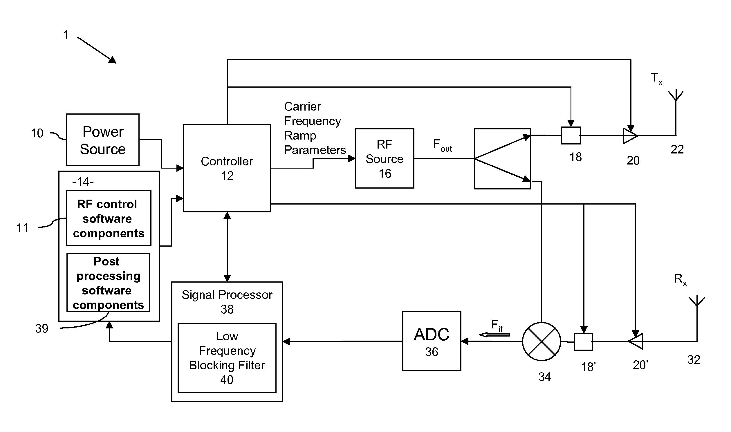
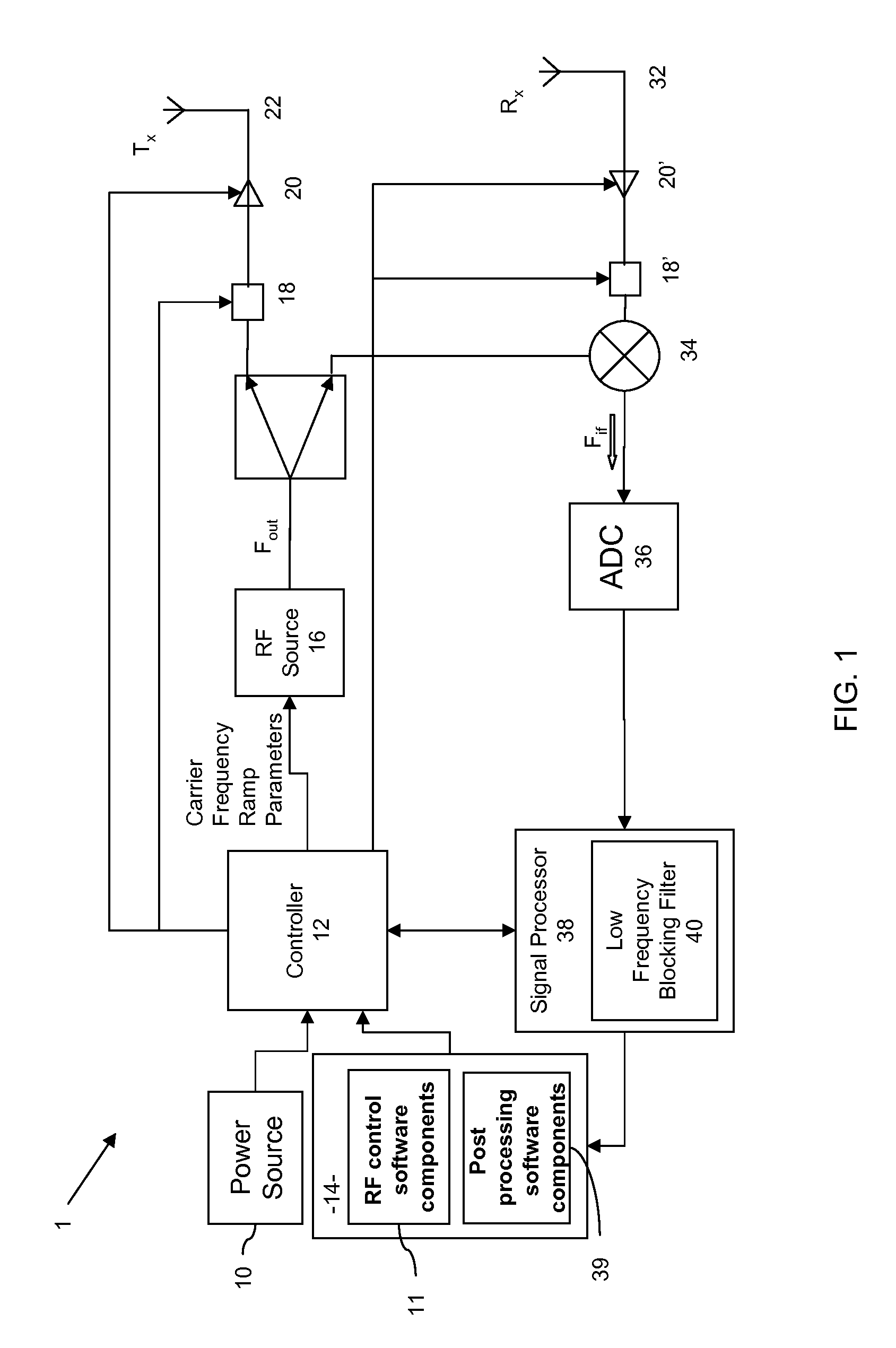
[0030]FIG. 1 shows a radar system 1 according to embodiments of the invention, comprising a power source 10, a controller 12, and a computer 14, the power source and computer 10, 14 being arranged to provide power to, and operational control over, the controller 12. As will be described in more detail below, in a first embodiment of the invention the antenna 22 is of the frequency scanning type, and the controller 12 comprises a microprocessor and a set of instructions (not shown) for execution thereby, effectively generating control signals that cause the RF frequency source, or signal generator 16, to output RF energy at a specified frequency FOUT; this output signal, under control of switches 18 and amplifiers 20, drives antenna 22 (whilst the Figure shows a switch component 18, it will be appreciated that in this particular arrangement—in which there is only one antenna 22—the switch 18 is inessential).

[0031]In this embodiment the radar system 1 also includes a receiving antenna...


PUM


Abstract

Electronically steered radar systems such as frequency scanning radars are particularly suitable for detecting and monitoring slow moving, ground-based targets. So-called crawler radar systems are intended for detection of targets that deliberately attempt to avoid detection by keeping low and by moving slowly. Disclosed is a radar system which includes an electronically steered antenna and a receiver arranged to process signals received from a target located at a distance from the radar system so as to identify a Doppler frequency associated with the target. The antenna stares at, rather than glides past, the target surrounding clutter. This means that the spectral spreading of static ground clutter associated with mechanical radar systems can be eliminated, overcoming one of the shortcomings of mechanical radar systems that would otherwise render a crawler radar system unsuitable for Doppler processing.

Description

CROSS REFERENCE TO RELATED APPLICATIONS[0001]This patent application is a Continuation of International Patent Application No. PCT / EP2007 / 064298 filed on Dec. 20, 2007 and entitled “RADAR SYSTEM”, the contents and teachings of which are hereby incorporated by reference in their entirety.FIELD OF THE INVENTION[0002]The present invention relates to a radar system, and relates specifically to electronically steered radar systems that are particularly, but not exclusively, suitable for detecting and monitoring slow moving, ground-based targets.BACKGROUND OF THE INVENTION[0003]Radar systems are used to detect the presence of objects and to measure the location and movement of objects. In general, radar systems are designed for a specific application: to measure distance over a specified range of distances; over a specified scan region; within a specified level of accuracy; and in relation to a specified orientation. So-called crawler radar systems are intended for detection of targets th...

Claims


Application Information

Patent Timeline
Patent Type & Authority Patents(United States)
IPC IPC(8): G01S13/536G01S13/538
CPCG01S13/5244G01S13/52G01S13/89
Inventor GREENDALE, STEVERADFORD, MARKSPREADBURY, DAVID
Owner BLIGHTER SURVEILLANCE SYST LTD
Why Eureka
Try Eureka