System and method for controlling supply fan speed within a variable air volume system

a technology of variable air volume and supply fan, which is applied in the direction of refrigeration components, process and machine control, refrigeration machines, etc., can solve the problems of system normal operation at inefficient levels, waste of energy, and greatly reduced energy efficiency of supply fans

Inactive Publication Date: 2013-07-09
WATSON DAVID STANLEY
View PDF49 Cites 45 Cited by
  • Summary
  • Abstract
  • Description
  • Claims
  • Application Information

AI Technical Summary

Problems solved by technology

Unfortunately, by using this method the energy efficiency of the supply fan is greatly reduced due to the friction losses due to partially closed terminal box dampers and within the duct system.
Since it common for VAV systems to operate under partial load conditions during the vast majority of hours of operation, such systems are normally operating at inefficient levels.
Although Bujak improves upon some of the energy inefficiencies of conventional VAV systems, the patent discloses several of its own limitations.
One of the most significant limitations is that even though the VAV system disclosed in Bujak uses an algorithm to ostensibly identify the zone of greatest demand, the algorithm always measures a static pressure at a single and fixed location...

Method used


Image

  • System and method for controlling supply fan speed within a variable air volume system
  • System and method for controlling supply fan speed within a variable air volume system
  • System and method for controlling supply fan speed within a variable air volume system

Examples


Embodiment Construction

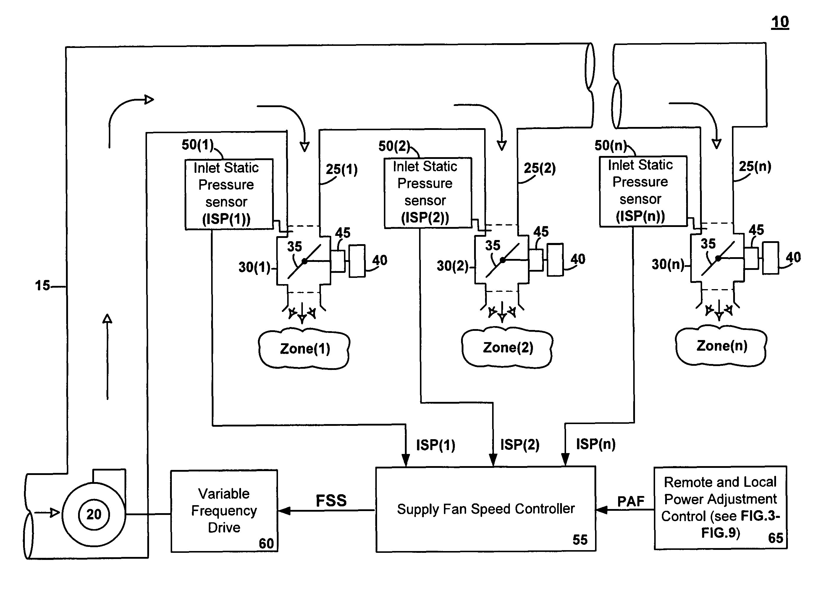
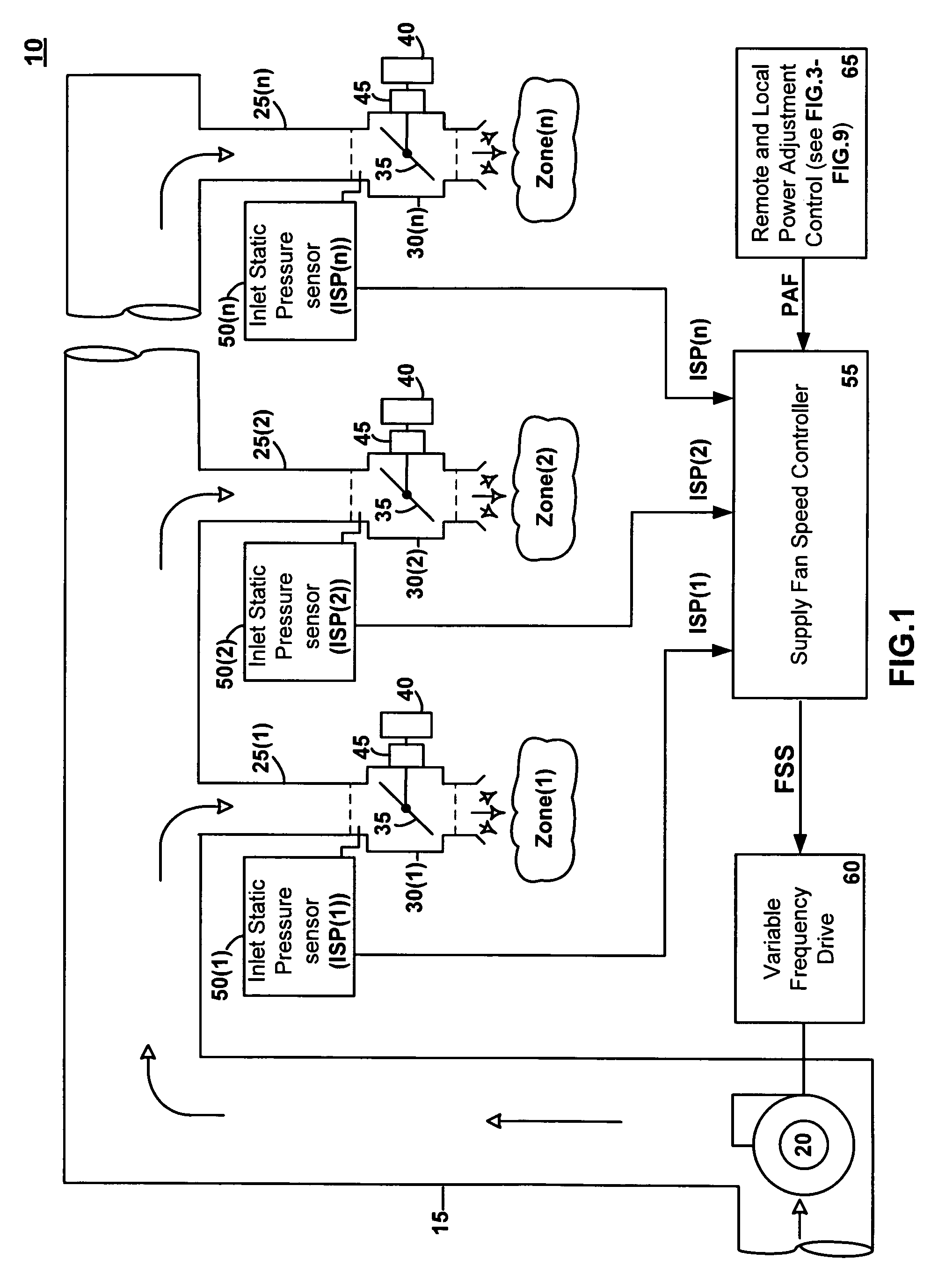
[0021]A preferred embodiment of a variable-air-volume system 10 is illustrated in FIG. 1 and FIG. 2. As shown in FIG. 1, system 10 includes a supply fan 20 that is utilized to supply conditioned air through a duct system and into a plurality of zones, illustrated as zone(1), zone(2) . . . zone (n), within a building. The duct system includes a main supply duct 15, a plurality of terminal supply ducts 25(1), 25(2) . . . 25(n), and a corresponding plurality of terminal boxes 30(1), 30(2) . . . 30(n). The outlet of supply fan 20 is connected to the inlet main supply duct 15. The plurality of terminal air supply ducts 25 are integral with the main supply duct 15, and the corresponding plurality of terminal boxes 30 are connected to the ends of terminal ducts 25. Each of terminal boxes 30 has an inlet and outlet opening, with an air control damper 35 disposed within each terminal box 30 and positioned between the inlet and outlet opening. The angular position of dampers 35 is controlled ...


PUM


Abstract

A variable-air-volume system for modulating the speed of a supply fan by measuring a plurality of inlet static pressures within the inlet of a corresponding plurality of terminal boxes within the system; calculating a plurality of setpoint errors equal to the difference between the plurality of inlet static pressures and a corresponding plurality of terminal box setpoint pressures; selecting minimum setpoint error out of all of the calculated setpoint errors; and modulating the fan speed as a function of the minimum setpoint error. The system can also utilize a power adjustment factor to modify the terminal box set point pressures.

Description

RELATED APPLICATION[0001]This application relates to and claims the benefit under 35 U.S.C. §119(e) of U.S. Provisional Application No. 61 / 268,872 filed on Jun. 16, 2009.TECHNICAL FIELD[0002]This application relates to systems and methods for controlling supply fan speed within a variable-air-volume system (“VAV system”) in response to the demand for heating, ventilating and air-conditioning within zones within a building.BACKGROUND[0003]Many buildings today utilize VAV systems to supply conditioned air to zones within the building. Normally, each will have numerous supply fans, with each fan associated with a duct system generally consisting of a main air supply duct that branches into several terminal supply ducts, with a terminal box at the terminus of each terminal supply duct. When the fans are being operated, conditioned air is continually moved through the duct system and into the zones within the building.[0004]Conventional VAV systems are typically designed to maintain a st...

Claims


Application Information

Patent Timeline
IPC IPC(8): G05D23/00F24F11/00B60H1/00B60S1/54F24F7/00G05D23/12
CPCF24F3/044F24F11/001F24F11/0079F24F11/04Y02B30/767F24F2011/0042F24F2011/0056Y02B30/746F24F2003/0446F24F11/30F24F2110/00F24F2110/40F24F2140/40F24F11/77F24F11/74Y02B30/70F24F11/62F24F11/47
Inventor WATSON, DAVID STANLEY
Owner WATSON DAVID STANLEY
Why Eureka
Try Eureka