Quasi open-end wrench

a technology of open-end wrenches and wrenches, which is applied in the field of open-end wrenches, can solve problems such as unaddressed

Inactive Publication Date: 2013-07-16
SWING ALAN HAMILTON
View PDF13 Cites 12 Cited by
  • Summary
  • Abstract
  • Description
  • Claims
  • Application Information

AI Technical Summary

Benefits of technology

[0013]A unique feature of the present invention is provided a relief at the intersections of the arcuate surfaces and the planar surface of the shank.
[0015]Another advantageous characteristic of the invention is if the user unwittingly applies pressure on the shank in a straight line instead of rotational, the fastener is pulled into the mouth of the wrench jaws thus keeping the wrench from slipping off the fastener.
[0016]Still, another feature of the invention is the ease of engaging a hexagonal fastener with the wrench head by using the mutual torqueing jaw as a guide.

Problems solved by technology

U.S. Pat. No. 5,307,713 relates to an open end wrench incorporating a protrusion on top of the wrench head to keep the wrench in contact with the fastener while repositioning the wrench, but does not address the problem of slipping off or rounding the fastener.

Method used


Image

  • Quasi open-end wrench
  • Quasi open-end wrench
  • Quasi open-end wrench

Examples


Embodiment Construction

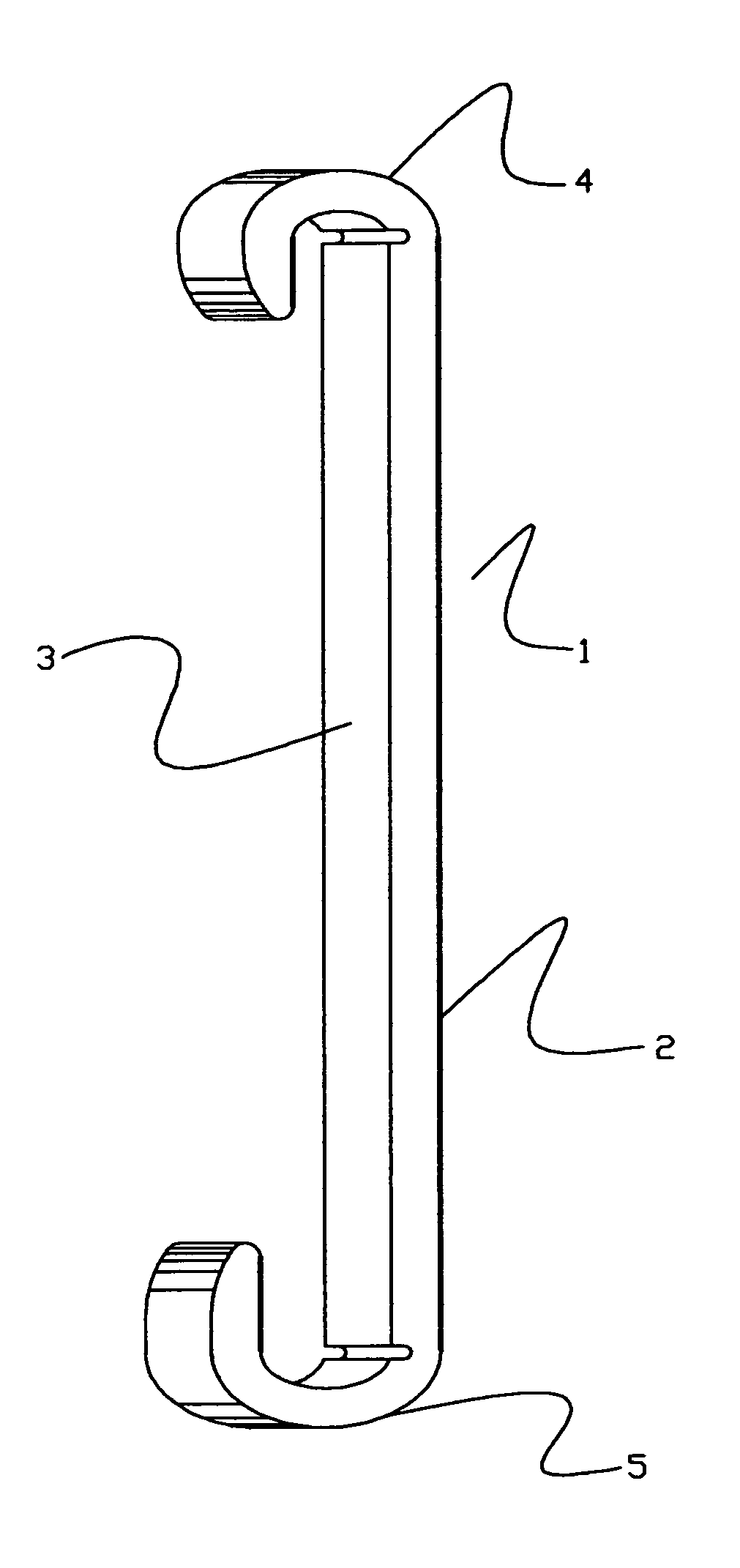
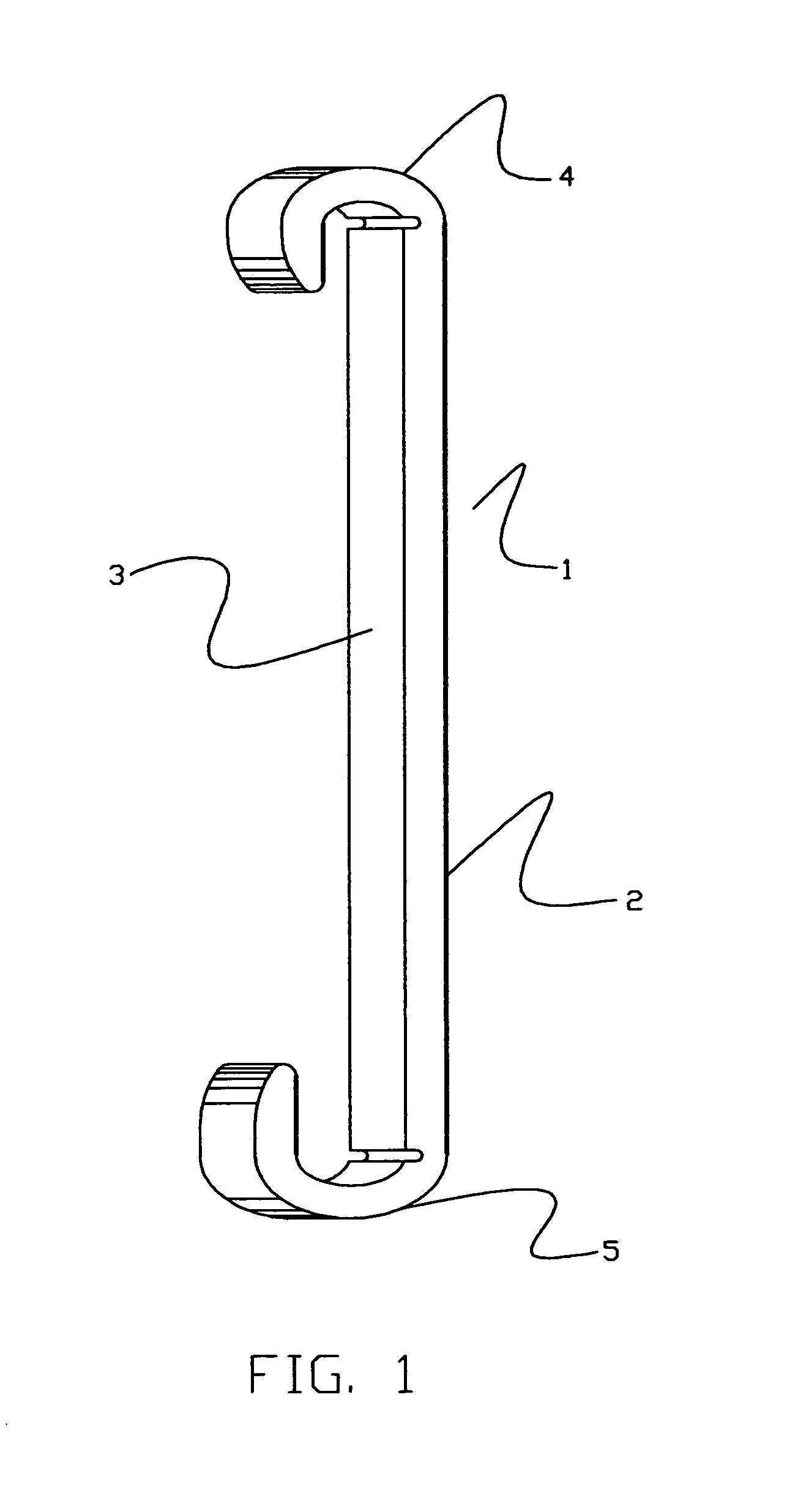
[0023]The preferred embodiment of the present invention is defined by FIGS. 1 through 5. FIG. 1 is an isometric illustrating an open-end wrench 1, having a shank 2 with a smooth planar surface 3, whereby planar surface 3 is the mutual torqueing jaw of fastener specific wrench heads 4 and 5.

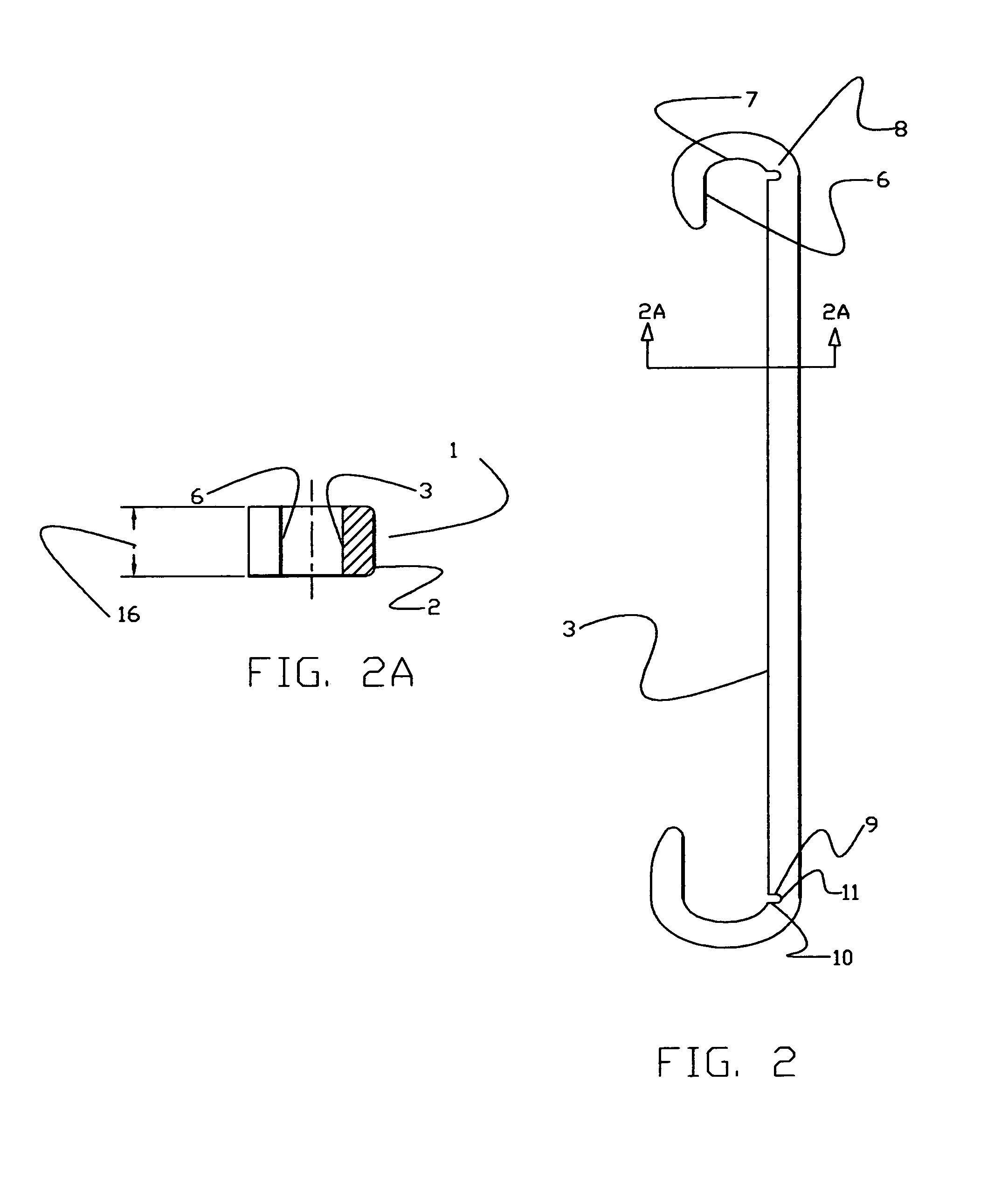
[0024]Shown in FIG. 2 is the location of section 2A, planer surface of backup jaw 6, arcuate surface 7 of wrench heads 4 and 5, and planar surfaces 9, 10 and arcuate surface 11 of relief 8.

[0025]Refereeing now to FIG. 2A showing above normal thickness 16 allowing for greater gripping surface to backup jaw 6 and torqueing jaw 3.

[0026]FIG. 3, shows center line 12, passing through the intersection of planar torqueing jaw 3 and arcuate surface 7, locating the relief 8, having depth 14 which is slightly less than half thickness 13 thereby weakening the structure at this point and giving flexible quality to shank 2 when torque is applied, thus making surfaces 9, 10 of relief 8 and wrench head surfaces 6...


PUM


Abstract

An improved open end wrench having wrench heads at both ends of a shank whereon both wrench heads have arcuate surfaces and backup jaws coplanar with a common torqueing jaw whereby the torqueing jaw is a machined surface of the wrench shank that extends into the wrench heads and is terminated at reliefs at a depth less than half the thickness of the shank, at the intersection of the arcuate surfaces and said torqueing jaw, therein, when excessive torque is applied the relief tends to close whereby the backup jaw and torqueing jaw become nonplanar to each other, therefore wedging the polygonal fastener being worked.

Description

REFERENCES CITED[0001]U.S. PATENT DOCUMENTS1,400,285December 1921Hart William Elijah5,148,726September 1992Huevschen6,009,778January 2000Hsieh5,307,713May 1994White5,172,614December 1992Monnet1,793,714April 1928E. Newberg3,447,405September 1967Lennon Et Al1,626,809December 1925Gillett2,652,735March 1949Wilder3,850,057November 1974Evans3,881,377May 1975Evans3,921,476November 1975Evans7,156,000January 2007Wroblewski, Lucien JBACKGROUND OF THE INVENTION[0002]This invention relates to typical open end wrenches with fixed heads thereby consisting of arcuate throats interconnecting planar jaws and specifically to the tendency of the wrench to slip off and / or round polygonal fasteners when torque is applied, insofar, when the torque applied isn'table to overcome the resistance of a polygonal fastener, the jaws of said wrench tend to spread apart rounding the fastener. In other cases the user tries to overcome the resistance of the polygonal fastener by unwittingly applying pressure on the ...

Claims


Application Information

Patent Timeline
Patent Type & Authority Patents(United States)
IPC IPC(8): B25B13/02B25B13/08
CPCB25B13/08
Inventor SWING, ALAN HAMILTON
Owner SWING ALAN HAMILTON
Why Eureka
Try Eureka