
Methods and apparatuses for inhibiting rotational misalignment of assemblies in expandable well tools

a technology of rotational misalignment and assembly, which is applied in the direction of drilling rods, drilling pipes, borehole/well accessories, etc., can solve the problems of collapsed outer diameter being significantly larger than intended, affecting the safety of extraction,

Active Publication Date: 2013-07-16
WWT NORTH AMERICA HLDG
View PDF225 Cites 11 Cited by
  • Summary
  • Abstract
  • Description
  • Claims
  • Application Information

AI Technical Summary

Benefits of technology

[0014]In some systems, rotation of an expandable assembly relative to other equipment, such as an wellbore engagement assembly, about a length of a gripper assembly could potentially inhibit or prevent the expandable assembly from being fully collapsed, resulting in the collapsed outer diameter being significantly larger than intended and potentially greater than would permit safe extraction. Thus, it may be desirable in some instances to inhibit or to prevent an expandable assembly from rotating relative to driving or other assemblies of a tractor or other downhole equipment. In some embodiments, the systems and methods of the present application can reduce or eliminate the possibility that an expandable assembly, such as a gripper, fail to adequately collapse or retract within a passage.

Problems solved by technology

In the event that an expandable mechanism fails to be properly collapsed or retracted, the expandable mechanism, other downhole equipment, the borehole or a combination of any of these may be damaged.
In some systems, rotation of an expandable assembly relative to other equipment, such as an wellbore engagement assembly, about a length of a gripper assembly could potentially inhibit or prevent the expandable assembly from being fully collapsed, resulting in the collapsed outer diameter being significantly larger than intended and potentially greater than would permit safe extraction.

Method used


Image

  • Methods and apparatuses for inhibiting rotational misalignment of assemblies in expandable well tools
  • Methods and apparatuses for inhibiting rotational misalignment of assemblies in expandable well tools
  • Methods and apparatuses for inhibiting rotational misalignment of assemblies in expandable well tools

Examples


Embodiment Construction

[0032]Some embodiments of methods and apparatuses for managing rotational alignment of assemblies of expandable well tools are described in the context of certain gripper assemblies. Nevertheless, the methods and apparatuses disclosed herein can be advantageously incorporated into other gripper assemblies and other types of expandable assemblies for downhole operation.

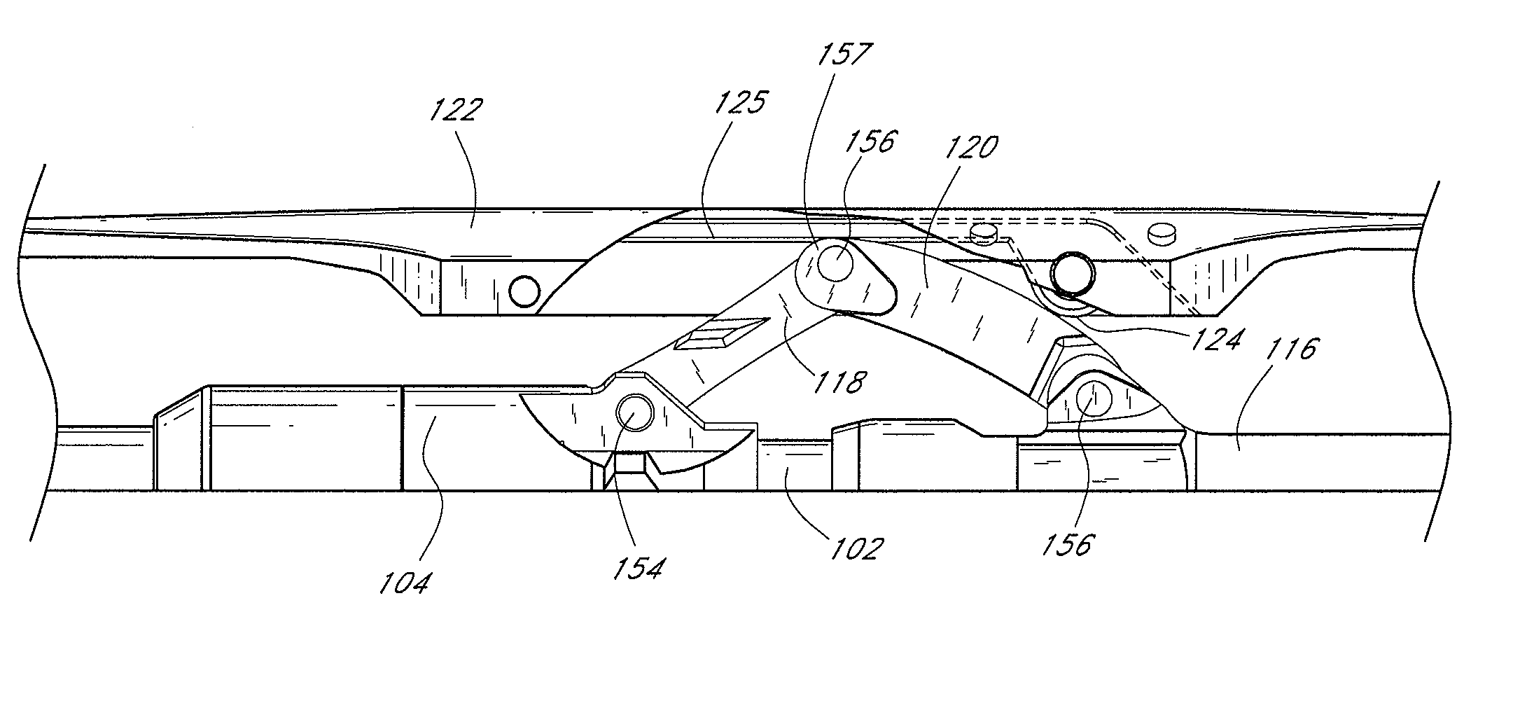
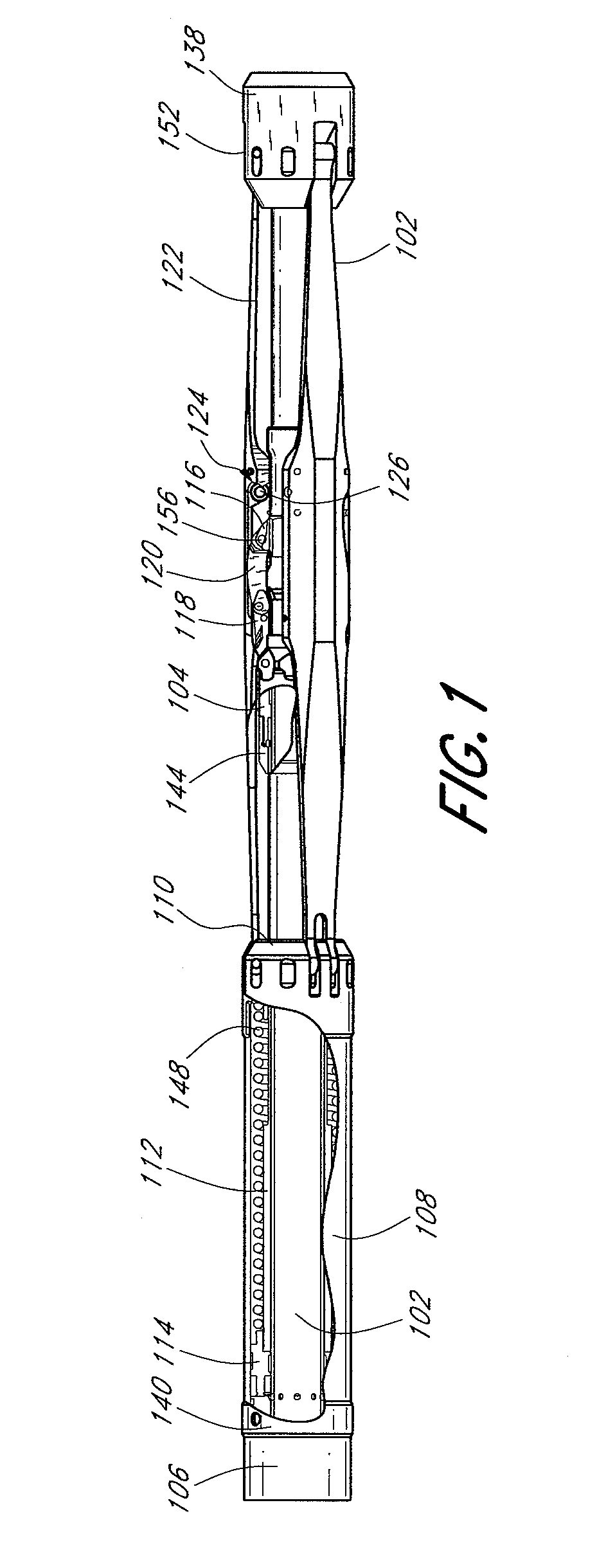
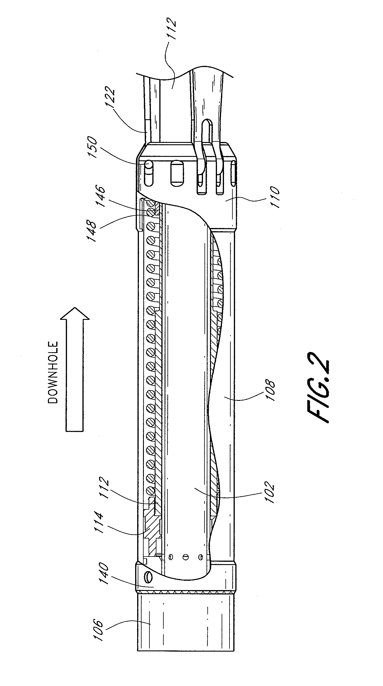
[0033]An Expandable Ramp Gripper or ERG is illustrated in FIGS. 1-9. The ERG can be configured to function by means of an expandable assembly applying a radial expansion force to an overlying engagement assembly to expand the engagement assembly. Details regarding the ERG, further to those provided herein, are provided in U.S. Pat. No. 7,624,808, entitled “Expandable Ramp Gripper,” which is hereby incorporated by reference herein in its entirety. The ERG can be positioned in a passage and operated in either axial orientation with respect to the uphole and downhole directions of a particular passage. However, as further...


PUM


Abstract

A gripper for use in a downhole tool is provided. The gripper can include an actuator, an engagement assembly, and an expandable assembly. The engagement assembly can comprise a leaf-spring like elongate continuous beam. The expandable assembly can comprise a linkage including a plurality of links. The linkage can be coupled to the actuator such that the actuator expands the expandable assembly which in turn expands the engagement assembly. One or more keyed connections can inhibit rotational misalignment of the expandable assembly from the engagement assembly. In operation, during one stage of expansion radial forces are transmitted to the engagement assembly through both interaction of a rolling mechanism on the engagement assembly with the expandable assembly and pressure of the linkage assembly directly on an inner surface of the engagement assembly. The one or more keyed connections can preferably facilitate full retraction of the expandable and engagement assemblies.

Description

CROSS-REFERENCE TO RELATED APPLICATIONS[0001]This application claims the benefit of U.S. Provisional Patent Application No. 61 / 246,955, entitled “EXPANDABLE RAMP GRIPPER,” filed on Sep. 29, 2009, and U.S. Provisional Patent Application No. 61 / 369,637, entitled “METHODS AND APPARATUSES FOR INHIBITING ROTATIONAL MISALIGNMENT OF ASSEMBLIES IN EXPANDABLE WELL TOOLS,” filed on Jul. 30, 2010. Also, this application hereby incorporates by reference both of the above-identified provisional applications in their entireties.BACKGROUND OF THE DISCLOSURE[0002]1. Field of the Disclosure[0003]This application relates generally to borehole tractors and gripping mechanisms for downhole tools.[0004]2. Description of the Related Art[0005]Tractors for moving within downhole passages are often required to operate in harsh environments and limited space. For example, boreholes for oil drilling typically are approximately 3.5-27.5 inches in diameter.[0006]Western Well Tool, Incorporated has developed a v...

Claims


Application Information

Patent Timeline
Patent Type & Authority Patents(United States)
IPC IPC(8): E21B23/04
CPCE21B4/18E21B23/04E21B23/042
Inventor MOCK, PHILIP W.
Owner WWT NORTH AMERICA HLDG
Learn More