Fixing mechanism and manipulator using the same

a technology of fixing mechanism and manipulator, which is applied in the field of manufacturing, can solve the problems of consuming more tim

Inactive Publication Date: 2013-07-16
HONG FU JIN PRECISION IND (SHENZHEN) CO LTD +1
View PDF21 Cites 11 Cited by
  • Summary
  • Abstract
  • Description
  • Claims
  • Application Information

AI Technical Summary

Benefits of technology

[0005]Generally, before polishing a workpiece such as a cover, the workpiece needs to be positioned securely. Typically, if the outer surface of the workpiece includes a curved portion and a planar portion, the workpiece is mainly positioned manually, which is very time-consuming. In addition, due to the curved and planar profiles of the workpiece, the outer surface of the workpiece cannot be completely polished in one process, requiring at least one repositioning, thereby consuming more time.

Problems solved by technology

Typically, if the outer surface of the workpiece includes a curved portion and a planar portion, the workpiece is mainly positioned manually, which is very time-consuming.
In addition, due to the curved and planar profiles of the workpiece, the outer surface of the workpiece cannot be completely polished in one process, requiring at least one repositioning, thereby consuming more time.

Method used


Image

  • Fixing mechanism and manipulator using the same
  • Fixing mechanism and manipulator using the same
  • Fixing mechanism and manipulator using the same

Examples


Embodiment Construction

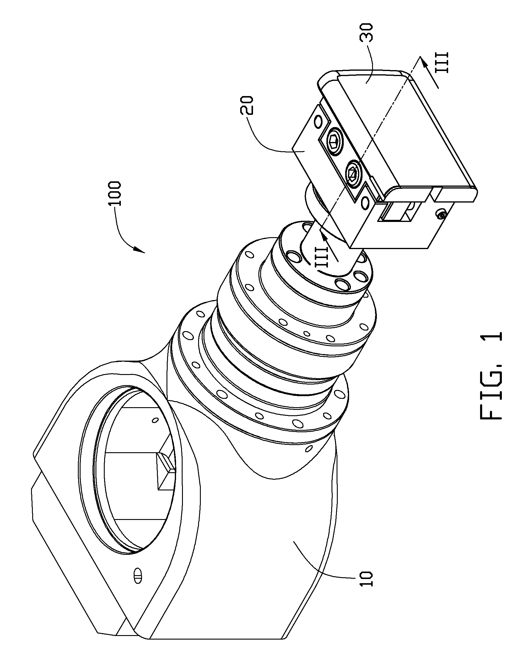
[0011]Referring to FIG. 1, an exemplary manipulator 100 is shown. The manipulator 100 includes a support arm 10 and a fixing mechanism 20. The fixing mechanism 20 is mounted on the support arm 10 to position a workpiece 30. The support arm 10 can move the fixing mechanism 20 and the workpiece 30. The manipulator 100 can be used with for example a polishing machine (not shown) to polish an outer surface of the workpiece 30.

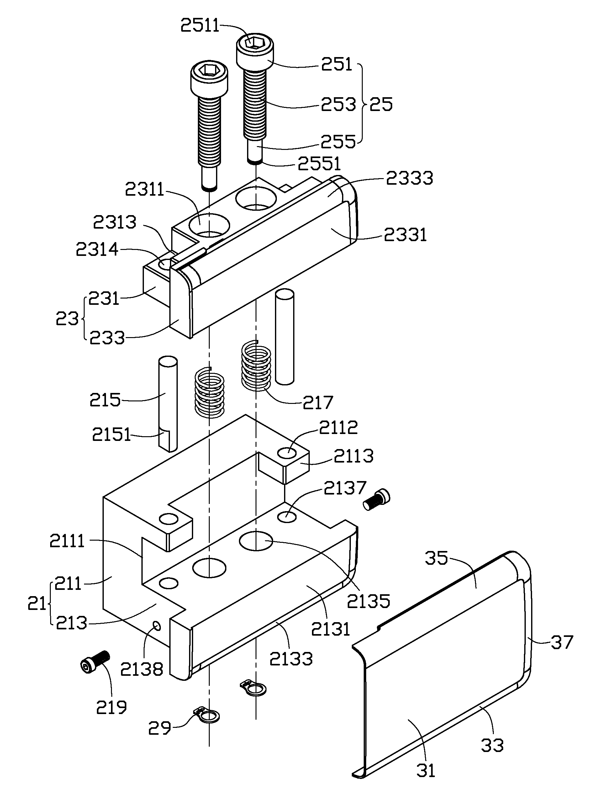
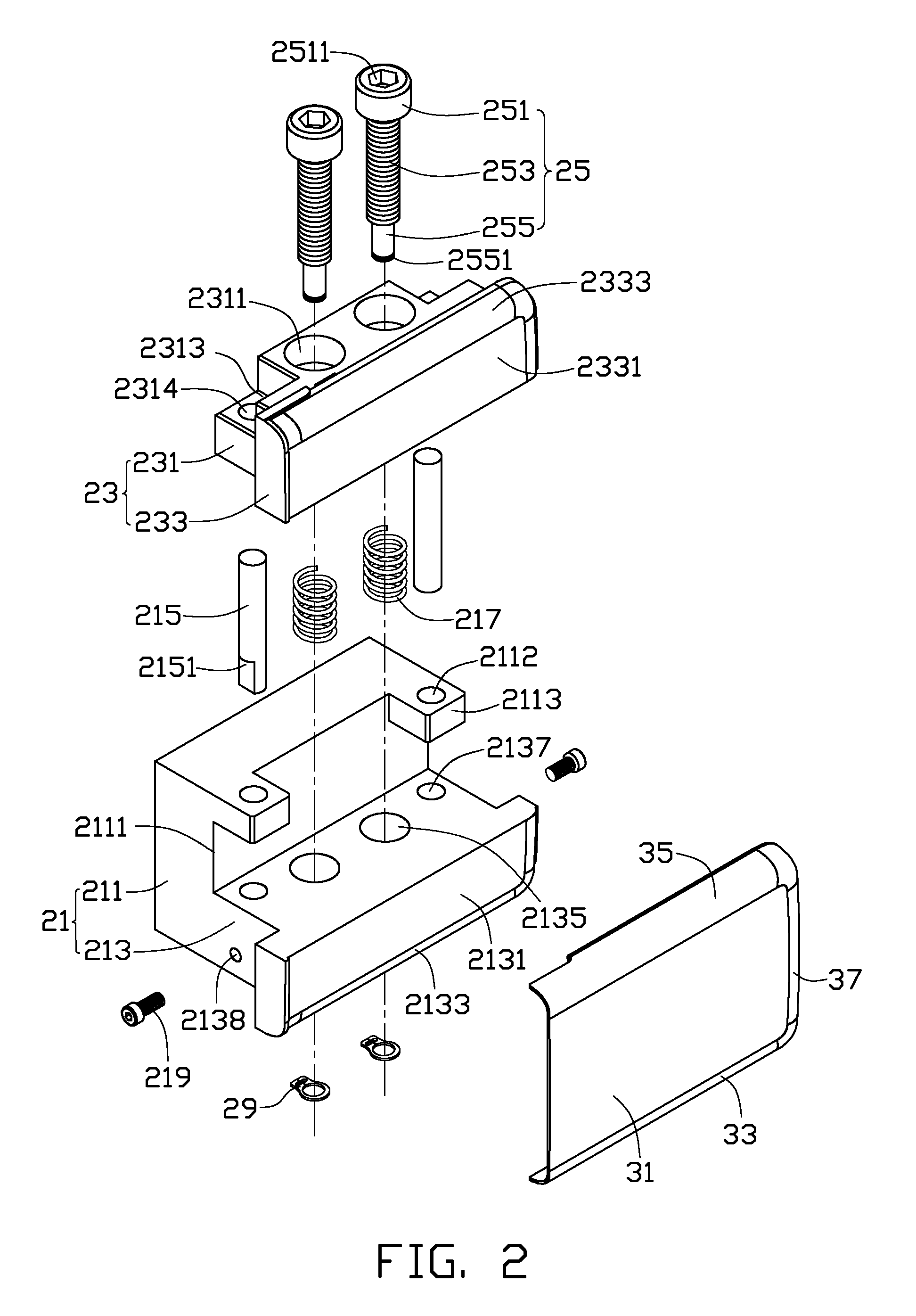
[0012]Referring to FIG. 2, the workpiece 30 includes a bottom board 31, a first sidewall 33, a second sidewall 35, and a third sidewall 37. The first sidewall 33, the second sidewall 35, and the third sidewall 37 extend from a periphery of the bottom board 31. The third sidewall 37 interconnects the first sidewall 33 and the second sidewall 35. The first side wall 33 faces the second sidewall 35. In the illustrated embodiment, all of the sidewalls 33, 35, 37 are curved.

[0013]The fixing mechanism 20 includes a fixed member 21, a movable member 23, and two driving me...


PUM


Abstract

A fixing mechanism includes a fixed member, a movable member, and a driving member. The fixed member has a first claw portion, and the movable member has a second claw portion. The movable member is movably connected to the fixed member via the driving member. The driving member is configured for moving the movable member in a direction away from the first claw portion of the fixed member. A manipulator using the fixing mechanism is also disclosed.

Description

BACKGROUND[0001]1. Technical Field[0002]The present disclosure relates generally to manufacturing, and more specifically, to a fixing mechanism for a manipulator.[0003]2. Description of Related Art[0004]Conventionally, to enhance mechanical strength and appearance of an electronic device, a metallic cover is provided with, often, a polished finish.[0005]Generally, before polishing a workpiece such as a cover, the workpiece needs to be positioned securely. Typically, if the outer surface of the workpiece includes a curved portion and a planar portion, the workpiece is mainly positioned manually, which is very time-consuming. In addition, due to the curved and planar profiles of the workpiece, the outer surface of the workpiece cannot be completely polished in one process, requiring at least one repositioning, thereby consuming more time.[0006]Therefore, there is room for improvement within the art.BRIEF DESCRIPTION OF THE DRAWINGS[0007]The components in the drawings are not necessari...

Claims


Application Information

Patent Timeline
Patent Type & Authority Patents(United States)
IPC IPC(8): B23Q3/02B23Q3/00B25B3/00
CPCB24B41/06B25J15/00
Inventor WANG, HUI
Owner HONG FU JIN PRECISION IND (SHENZHEN) CO LTD
Why Eureka
Try Eureka