
Internal locking apparatus and methods for making and using same

a technology for locking containers and containers, applied in anti-theft devices, programs, instruments, etc., can solve the problems of voiding the lease agreement, unauthorized and undetectable opening of locks, and cost prohibitive drilling into trailers or containers, etc., to achieve increased security, increase security, and increase the effect of time-consuming

Inactive Publication Date: 2007-05-17
INNERLOC
View PDF42 Cites 41 Cited by
  • Summary
  • Abstract
  • Description
  • Claims
  • Application Information

AI Technical Summary

Benefits of technology

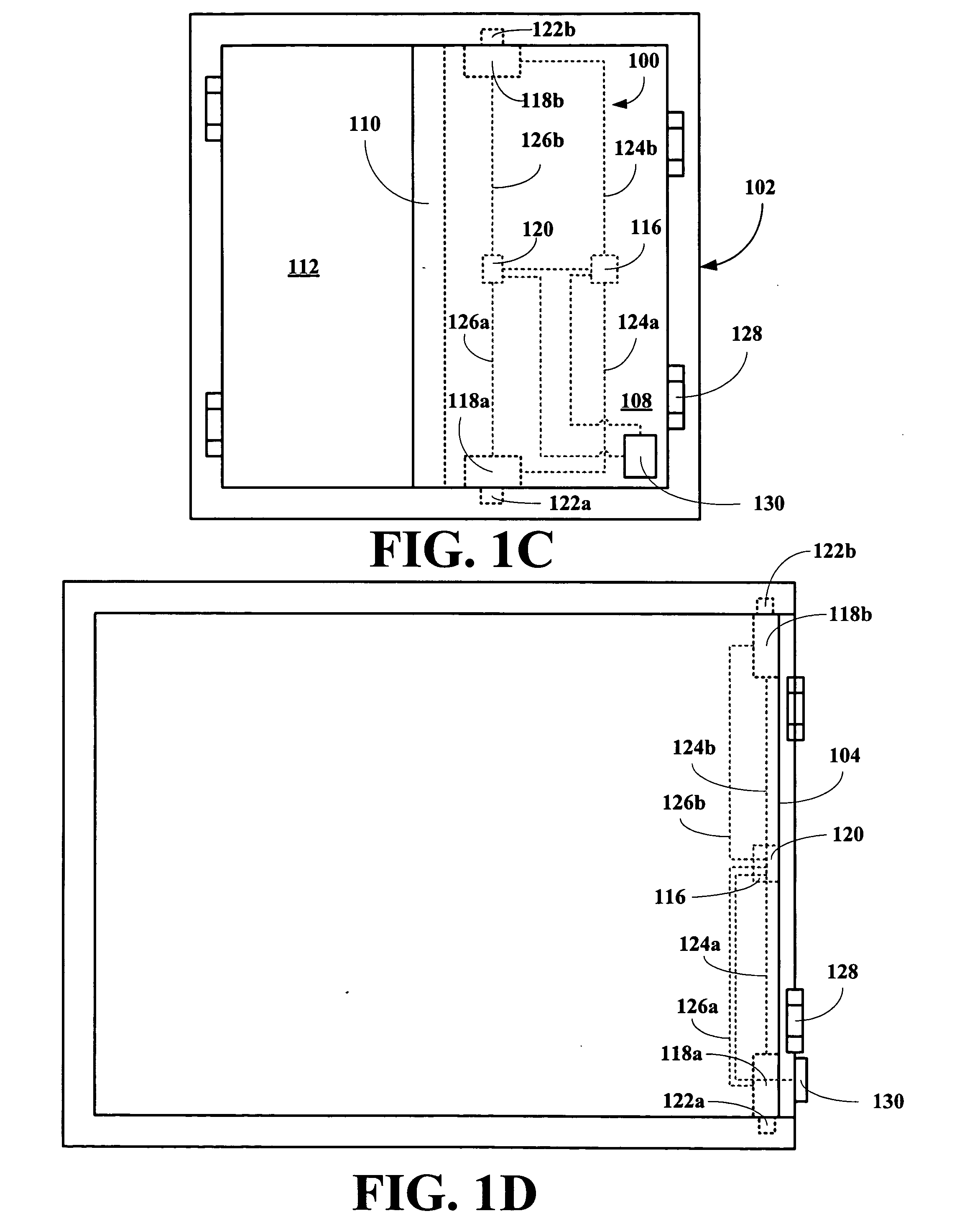
[0011] The apparatus can also include a plurality of locking systems. In the case of apparatuses that include multiple locking systems, each locking system will have its own drive. When the locking systems are independently controlled, then security is higher, but manual locking and / or unlocking are more time consuming. Of course, if the locking systems are controlled via telemetry (Rf, IR, nearIR, sonic, microwave, radar, etc.), then each locking system can be on a separate frequency, have a separate code or a combination, thereof to further increase security, yet not slowing down locking and unlocking operations.

Problems solved by technology

The lack of internal voids or external pockets will also prevent of wire-based devices to manually manipulate the microprocessor or electronics to result in the unauthorized and undetectable opening of the lock.
As 60% of the domestic market constitutes leased trailer or containers and drilling into the trailer or container is cost prohibitive and potentially voids the lease agreement.
First, such power jacks require a breach of the trailer or container interior.

Method used


Image

  • Internal locking apparatus and methods for making and using same
  • Internal locking apparatus and methods for making and using same
  • Internal locking apparatus and methods for making and using same

Examples


Embodiment Construction

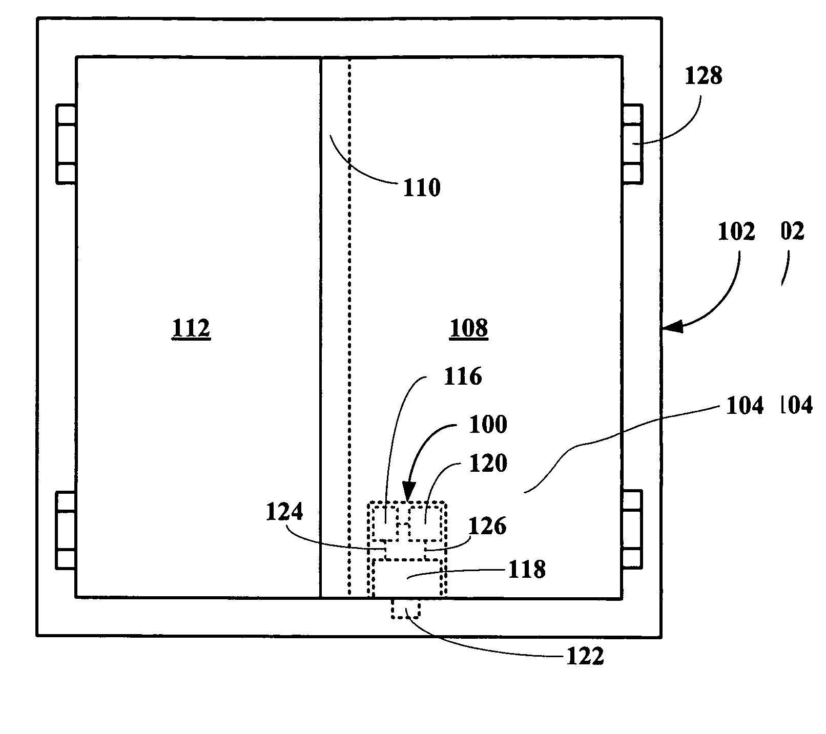
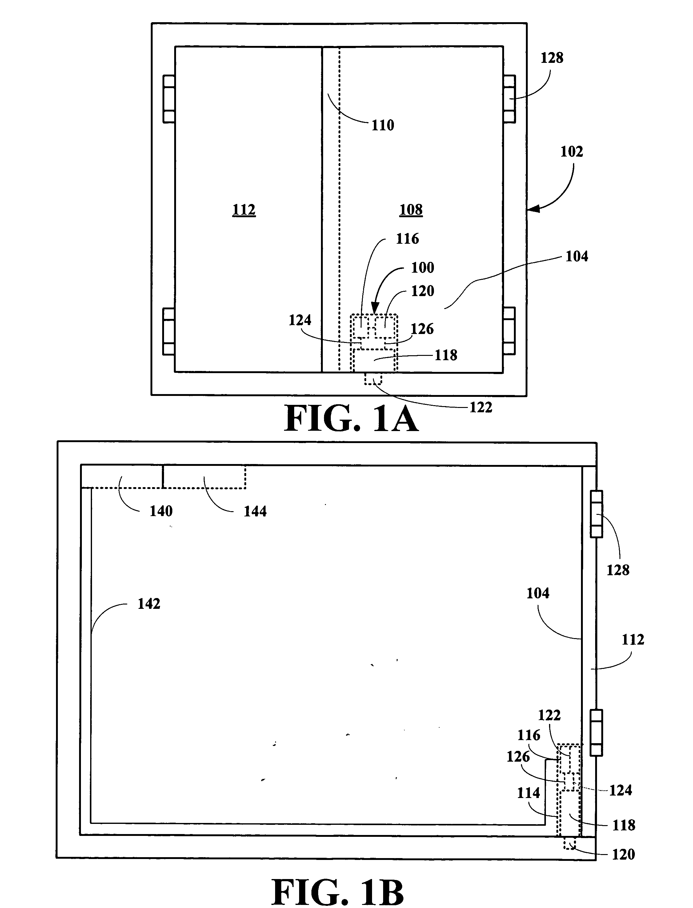
[0025] The inventors have found that a locking apparatus for any container accessible by a door or an opening can be installed within an interior of the container, where the locking apparatus permits the door or opening to be locked from the inside so increase container security. The inventors have found that a electromechanical drive system provides superior performance, superior reliability, is compact and easily serviced.

[0026] The present invention broadly relates to an internal locking apparatus including a electro-mechanical locking system and an electronic control system. The locking system includes an electro-mechanical locking assembly and a source of electrical energy for powering in electrical communication with the locking assembly, while the electronic control system is in electrical communication with the locking system and controls the locking system. The locking assembly moves between a retracted position (an unlocked position) and an extended position (a locked pos...


PUM


Abstract

An internal locking system is disclosed, which utilizes electromechanical locking devices to lock and unlock lockable openings.

Description

RELATED APPLICATIONS [0001] This application claims priority of U.S. patent application Ser. No. 11 / 509,333 filed Aug. 24, 2006, which claims priority to U.S. Provisional Patent Application Ser. No. 60 / 710,755, filed Aug. 24, 2005.BACKGROUND OF THE INVENTION [0002] 1. Field of the Invention [0003] The present invention relates to an apparatus for locking containers from the inside and to methods for making and using same. [0004] More particularly, the present invention relates to an apparatus for locking containers from the inside, where the apparatus locking assembly selected from the group consisting of worm screw drives, linear actuator drives, cam drive, or the like, and a remotely accessible control assembly and to methods for making and using same. [0005] 2. Description of the Related Art [0006] Although most doors are locked on the outside using a variety of locking mechanisms, such outside locking devices are prone to unwanted and / or unlawfully enter either by tampering with...

Claims


Application Information

Patent Timeline
Patent Type & Authority Applications(United States)
IPC IPC(8): B60R25/00
CPCE05B47/026E05B83/02E05B2047/0058E05B81/52E05B47/0001E05B47/0012E05B2047/002Y10T70/7062
Inventor COUTERMARSH, RICHARD ALFREDEASTMAN, JOHN REID
Owner INNERLOC
Learn More