Method for removal of bone

a bone and arthroplasty technology, applied in the field of orthopaedics, can solve the problems of sacrificing the anterior talus, removing too much bone, and difficult to do, and achieve the effect of removing accurate and repeatable keel slots, and reducing the chance of anterior talus fractur

Inactive Publication Date: 2013-07-23
DEPUY SYNTHES PROD INC
View PDF174 Cites 33 Cited by
  • Summary
  • Abstract
  • Description
  • Claims
  • Application Information

AI Technical Summary

Benefits of technology

[0021]The technical advantage of the present invention includes a subsurface angled ramp and subsurface return arch which cradles and lets the burr rotate out of the burr guide. Another advantage of the present invention is the ability to utilize different burring angle positions to allow the user to burr under the tibia when the tibia and talar are at less than a 900 relative position.
[0022]In another aspect of an embodiment of the present invention, a flat bottom trough may be created with the burr and burring guide without the burr being perpendicular to the burring guide.
[0023]A further aspect of an embodiment of the present invention is that the anterior cortex of the talus may be preserved utilizing this surgical technique and related instrumentation. The technique leaves the cortices intact providing a sound bone construct for implant stability, and removes the chance of fracturing the anterior cortex.
[0024]Another aspect of an embodiment of the present invention is that accurate and repeatable keel slots may be provided without the same degree of experience and skill required for freehand reciprocating saw procedures.

Problems solved by technology

The current procedure utilizes a reciprocating saw which is difficult to do, is not repeatable and possibly removes too much bone and sacrifices the talus anterior cortex.

Method used


Image

  • Method for removal of bone
  • Method for removal of bone
  • Method for removal of bone

Examples


Embodiment Construction

[0048]Embodiments of the present invention and the advantages thereof are best understood by referring to the following descriptions and drawings, wherein like numerals are used for like and corresponding parts of the drawings.

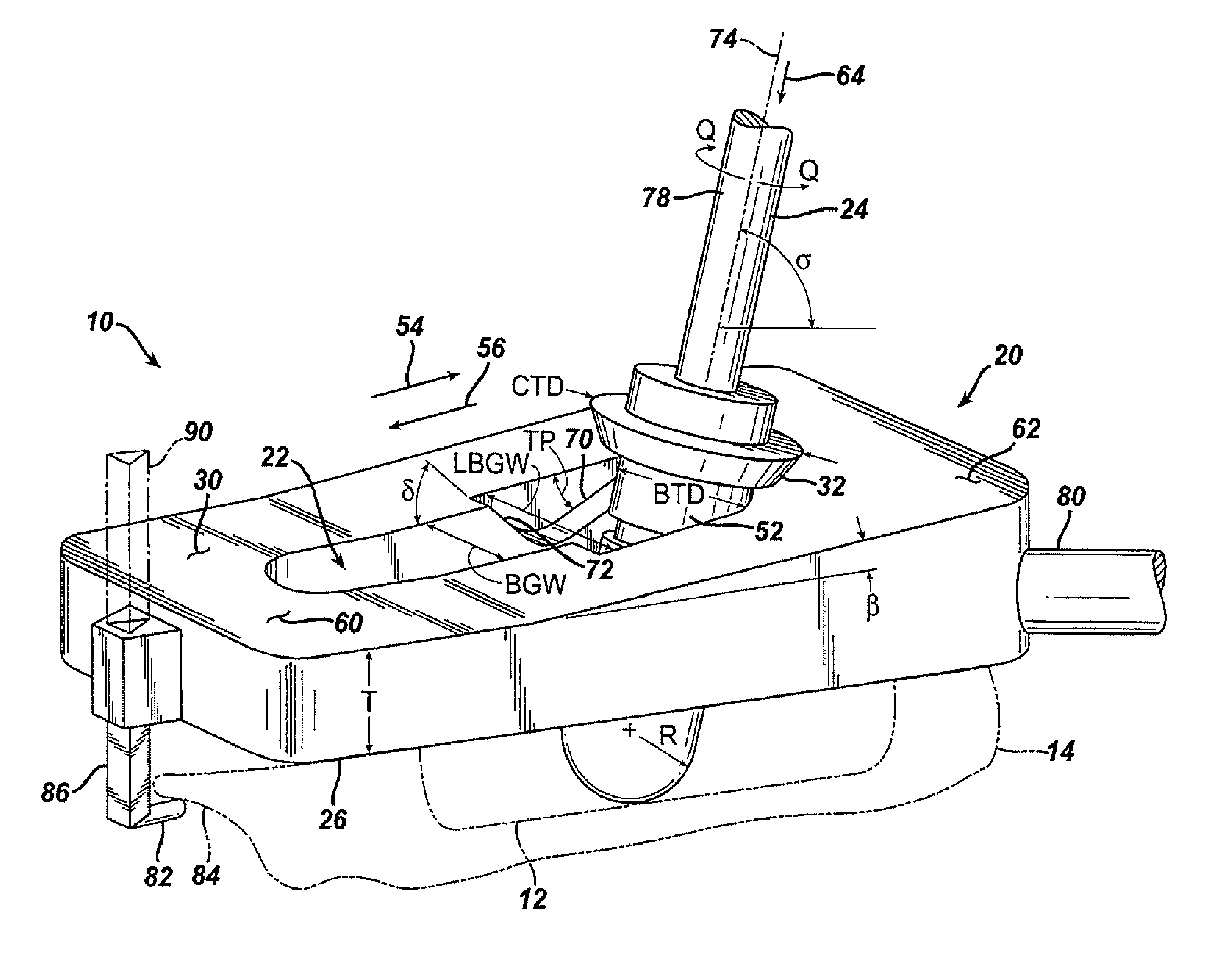
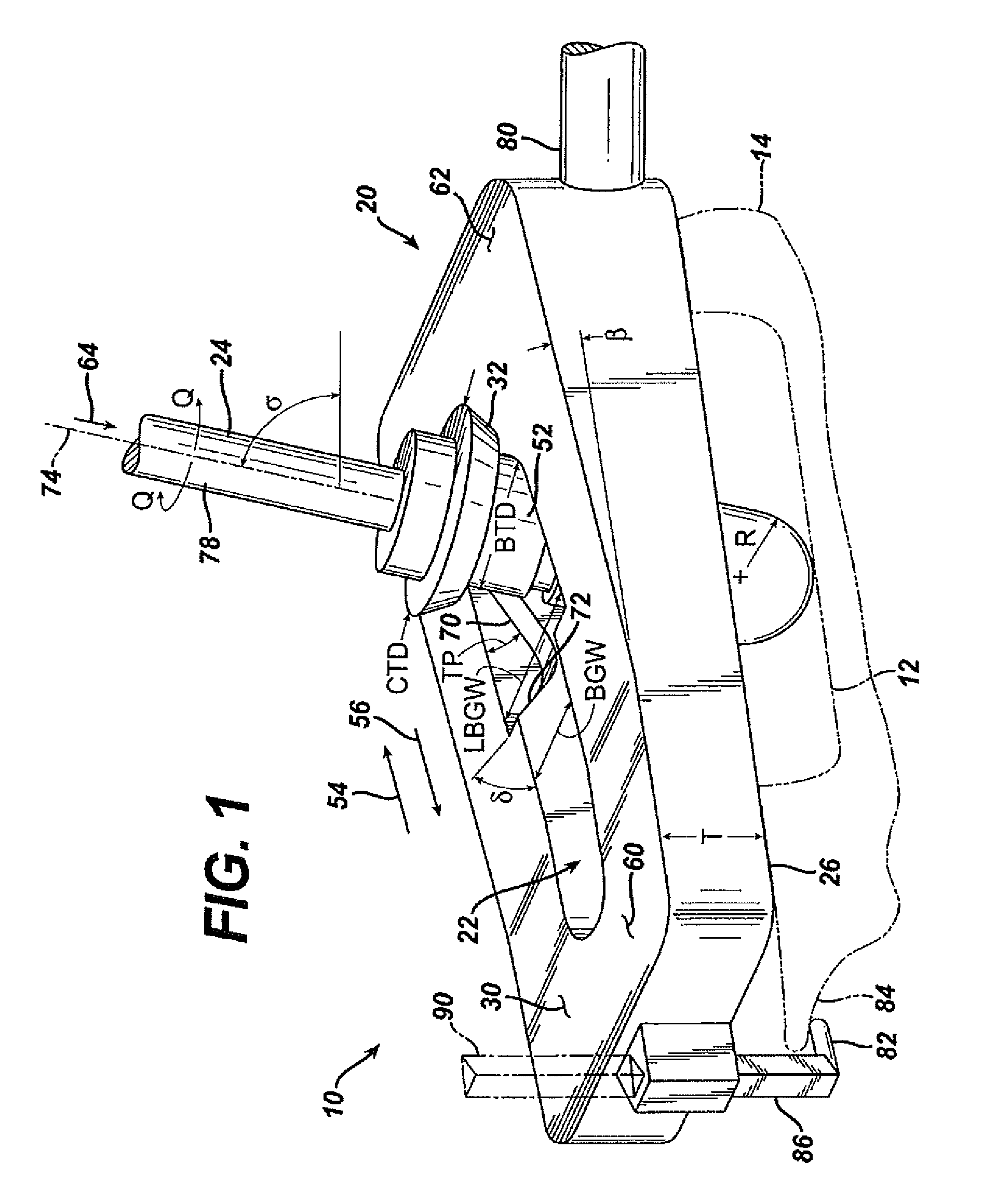
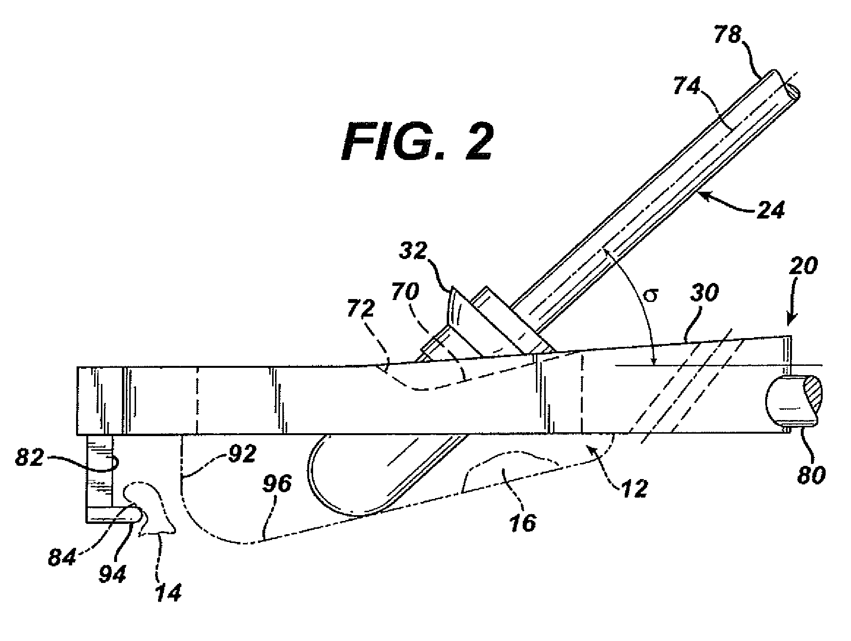
[0049]According to the present invention and referring now to FIG. 1, an embodiment of the present invention is shown as kit 10. Kit 10 is utilized for preparation of bone cavity 12 for implementation of a joint prosthesis (see FIGS. 19-21). The kit 10 includes a guide 20 which defines an opening 22 through the guide 20. The kit 10 further includes a rotatable tool 24 adapted to be constrainable within the opening 22 of the guide 20. The tool 24 is adapted for removal of bone 14 to form the bone cavity 12.

[0050]The guide 20 may define a first surface 26 of the guide 20 for cooperation with the bone 14. The guide 20 may also include a second surface 30 which is spaced from and may be parallel to the first surface 26. The tool 24 may include a collar 32 for coop...


PUM


Abstract

A kit (10) for preparation of a bone cavity (12) in a bone (14) for implantation of a joint prosthesis (16) is provided. The kit (10) includes a guide (20) defining an opening (22) therethrough. The guide (20) is in cooperation with the prosthesis. The kit (10) also includes a rotatable tool (24) constrainable within the opening (22) of said guide (20). The tool (24) is adapted for removal of bone (14) to form the bone cavity (12).

Description

[0001]This application is a continuation of co-pending application Ser. No. 10 / 177,966, filed on Jun. 21, 2002, the disclosure of which is herein totally incorporated by reference in its entirety.CROSS-REFERENCE TO RELATED APPLICATIONS[0002]This application is a Continuation of U.S. patent application Ser. No. 10 / 177,966, filed Jun. 21, 2002 (now abandoned). Cross reference is also made to U.S. application Ser. No. 10 / 176,934, filed Jun. 21, 2002 and entitled “PROSTHESIS REMOVAL CUTTING GUIDE, CUTTING TOOL AND METHOD” (now U.S. Pat. No. 7,935,118 issued May 3, 2011) and U.S. application Ser. No. 10 / 176,891, filed Jun. 21, 2002 and entitled “PROSTHESIS CUTTING GUIDE, CUTTING TOOL AND METHOD” (now U.S. Pat. 8,211,113 issued Jul. 3, 2012, the disclosures of which are incorporated herein by reference.TECHNICAL FIELD OF THE INVENTION[0003]The present invention relates generally to the field of orthopaedics, and more particularly, to an implant for use in arthroplasty.BACKGROUND OF THE IN...

Claims


Application Information

Patent Timeline
Patent Type & Authority Patents(United States)
IPC IPC(8): A61B17/58A61B17/60A61F2/00A61B17/16A61B17/17
CPCA61B17/1682A61B17/1675A61B17/1764A61B2017/1775A61B17/1775
Inventor LONG, JACKMARONEY, BRIANGUZMAN, JOSEALVINE, FRANK G.CONTI, STEPHEN F.SANDERS, ROY W.
Owner DEPUY SYNTHES PROD INC
Why Eureka
Try Eureka