
Hot-fill container having movable ribs for accommodating vacuum forces

a vacuum force and hot-fill container technology, applied in the field of plastic containers, can solve the problems of conventional plastic containers that are cylindrical in profile, do not include a sidewall design with adequate vertical load bearing and dent resistance capabilities and properties, and achieve the effect of reducing the number of blown containers

Active Publication Date: 2013-07-30
AMCOR RIGID PLASICS USA LLC
View PDF18 Cites 20 Cited by
  • Summary
  • Abstract
  • Description
  • Claims
  • Application Information

AI Technical Summary

Benefits of technology

The present invention is related to a plastic container with a finish and a shoulder region merging into a sidewall portion. The sidewall portion can have horizontal lands and ribs extending from the shoulder region to a base portion having a base. The finish can have a means for attaching a closure thereon. The container is made of polyethylene terephthalate and is biaxially oriented. The technical effects of this invention include improved strength and durability of the plastic container, as well as a unique and stable attachment point for closures.

Problems solved by technology

In other examples, conventional plastic containers that are cylindrical in profile, do not include a sidewall design with adequate vertical load bearing and dent resistance capabilities and properties.

Method used


Image

  • Hot-fill container having movable ribs for accommodating vacuum forces
  • Hot-fill container having movable ribs for accommodating vacuum forces
  • Hot-fill container having movable ribs for accommodating vacuum forces

Examples


Embodiment Construction

[0020]The following description is merely exemplary in nature, and is in no way intended to limit the disclosure or its application or uses.

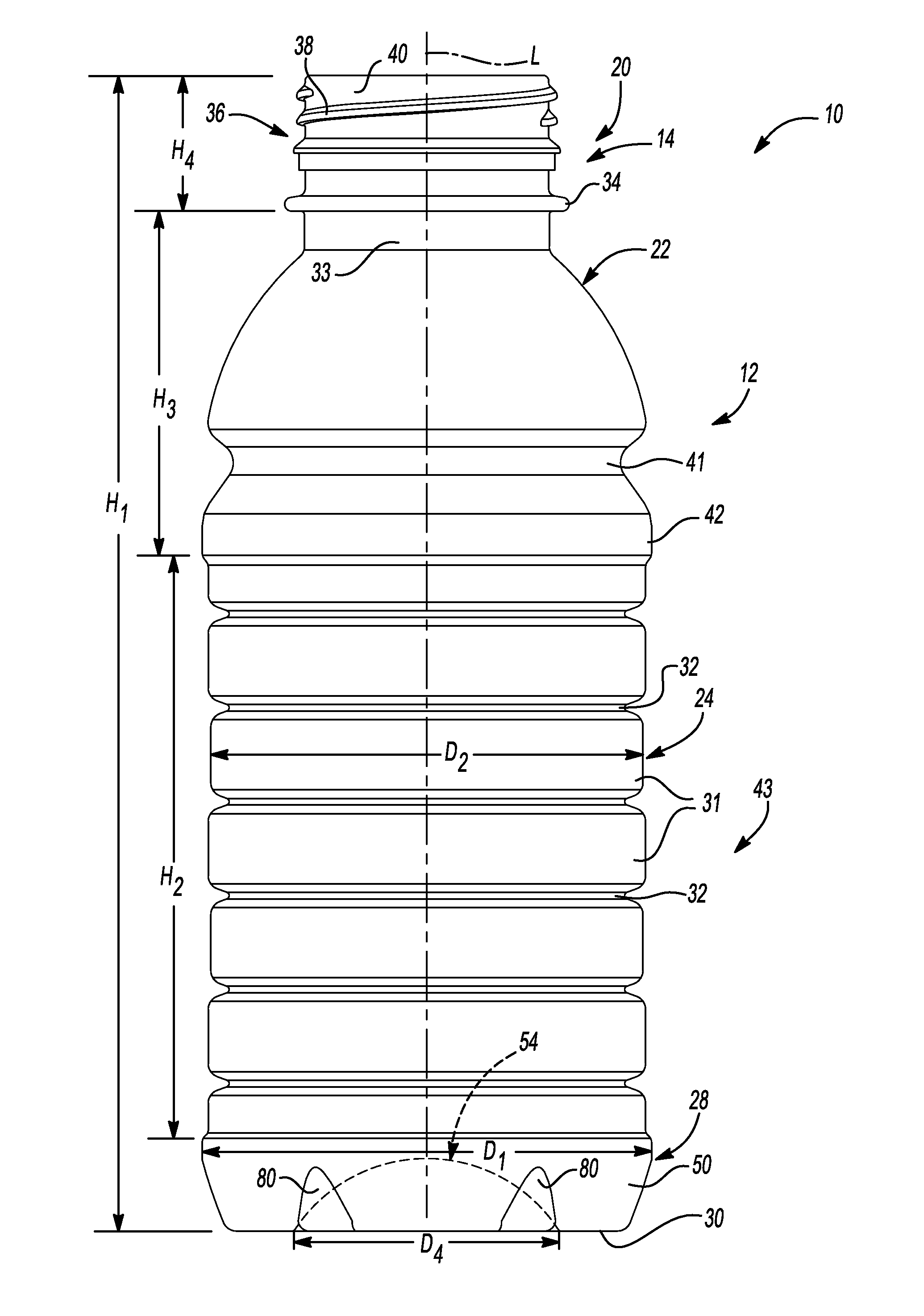
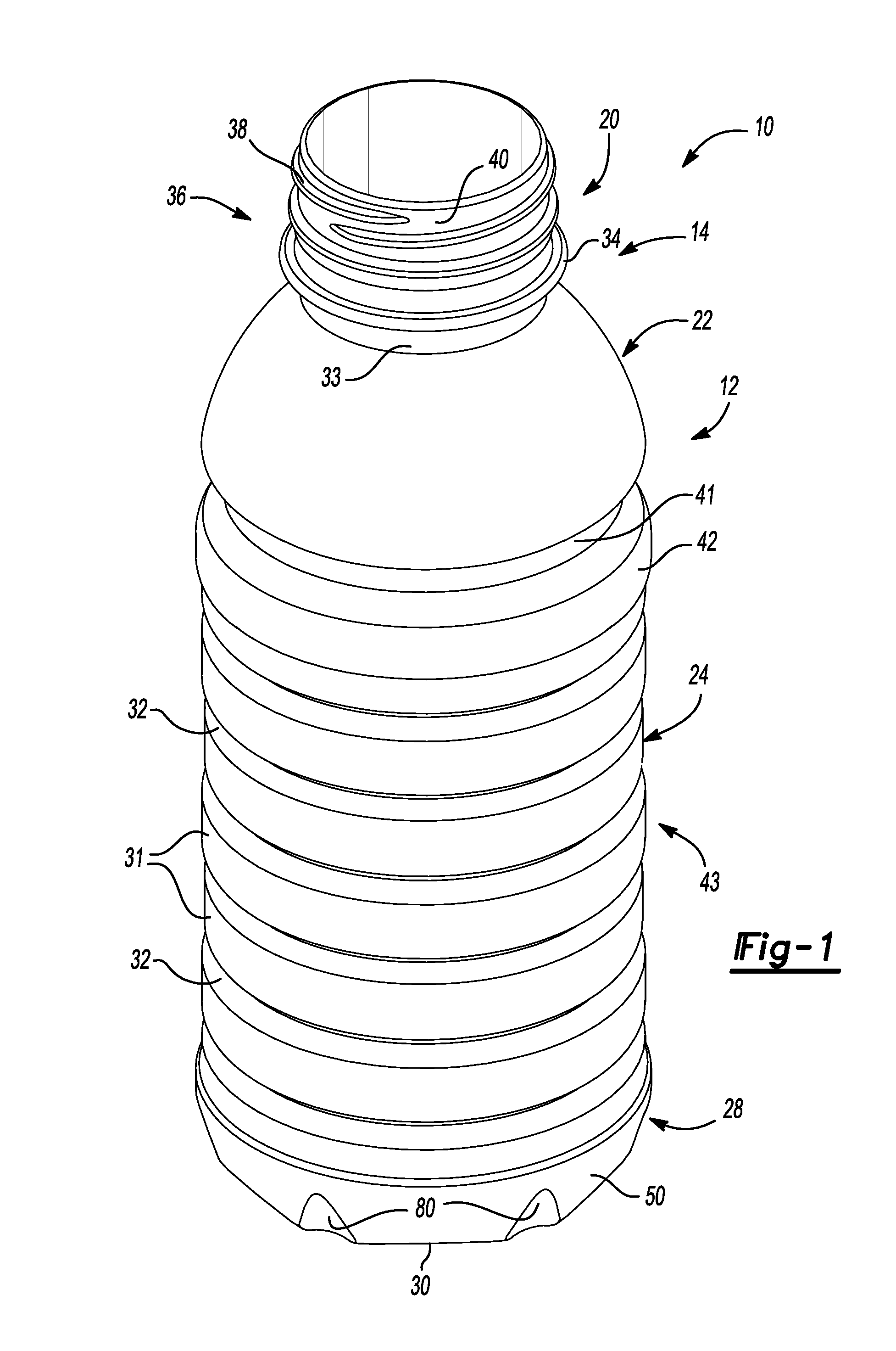
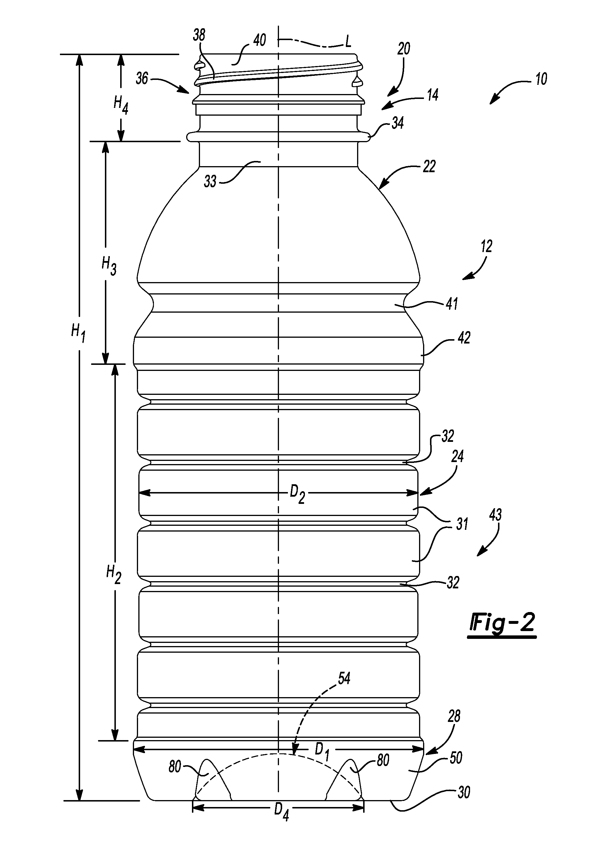
[0021]FIGS. 1-4, 6 and 7 show one preferred embodiment of the present container. In the Figures, reference number 10 designates a one-piece plastic, e.g. polyethylene terephthalate (PET), container. The plastic container 10 can define a longitudinal axis L (FIG. 2) and be substantially cylindrical in cross section. In this particular embodiment, the plastic container 10 has a volume capacity of about 20 fl. oz. (591 cc). Those of ordinary skill in the art would appreciate that the following teachings of the present disclosure are applicable to other containers, such as rectangular, triangular, hexagonal, octagonal or square shaped containers, which may have different dimensions and volume capacities. It is also contemplated that other modifications can be made depending on the specific application and environmental requirements.

[0022]As shown in...


PUM

PropertyMeasurementUnit
radiusaaaaaaaaaa
radiusaaaaaaaaaa
inner radiusaaaaaaaaaa

Abstract

A one-piece plastic container includes a container body and an upper portion having a finish. Integrally formed with the finish and extending downward therefrom is a shoulder region. The shoulder region merges into and provides a transition between the finish and a sidewall portion. The sidewall portion extends downward from the shoulder region to a base portion having a base. The sidewall portion defines a series of horizontal lands and horizontal ribs. The horizontal lands and horizontal ribs extend continuously in a vertical direction from the shoulder region to the base portion. The horizontal ribs are designed to achieve optimal performance with regard to vacuum absorption, top load strength capabilities and dent resistance.

Description

CROSS-REFERENCE TO RELATED APPLICATIONS[0001]This application claims the benefit of U.S. Provisional Application No. 61 / 127,621, filed on May 14, 2008. The entire disclosure of which is incorporated herein by reference.TECHNICAL FIELD[0002]This disclosure generally relates to plastic containers for retaining a commodity, such as a solid or liquid commodity. More specifically, this disclosure relates to a one-piece blown container having a series of horizontal ribs designed to achieve optimal performance with regard to vacuum absorption, top load strength capabilities and dent resistance.BACKGROUND[0003]As a result of environmental and other concerns, plastic containers, more specifically polyester and even more specifically polyethylene terephthalate (PET) containers are now being used more than ever to package numerous commodities previously supplied in glass containers. Manufacturers and fillers, as well as consumers, have recognized that PET containers are lightweight, inexpensiv...

Claims


Application Information

Patent Timeline
Patent Type & Authority Patents(United States)
IPC IPC(8): B65D1/46B29C49/10
CPCB65D1/0223B65D2501/0036B29K2023/065B65D79/0084B29C2949/26B29B11/08B29B11/14B29C49/06B29C49/12B29K2023/12B29K2067/00B29K2105/258B29L2031/7158B65D1/0261B29C2949/3008B29C2949/3012B29C2949/3026B29C2949/302B29C2949/3016B29C2949/3024B29C2949/28B29C2949/24B29C2949/22B29C2949/3032B29C2949/3034B29C2949/073B29C2949/0777B29C2949/0773B29C2949/0831B29C49/071B29C2949/0715B29C2049/7831B29C2049/7862B29C2049/78645
Inventor LANE, MICHAEL T.JOSHI, ROHIT V.SIMON, JOHN B.
Owner AMCOR RIGID PLASICS USA LLC
Learn More